AeroTower Electronics
The circuit of the tower is based on ordinary breadboards to be easily extendable and accessible.
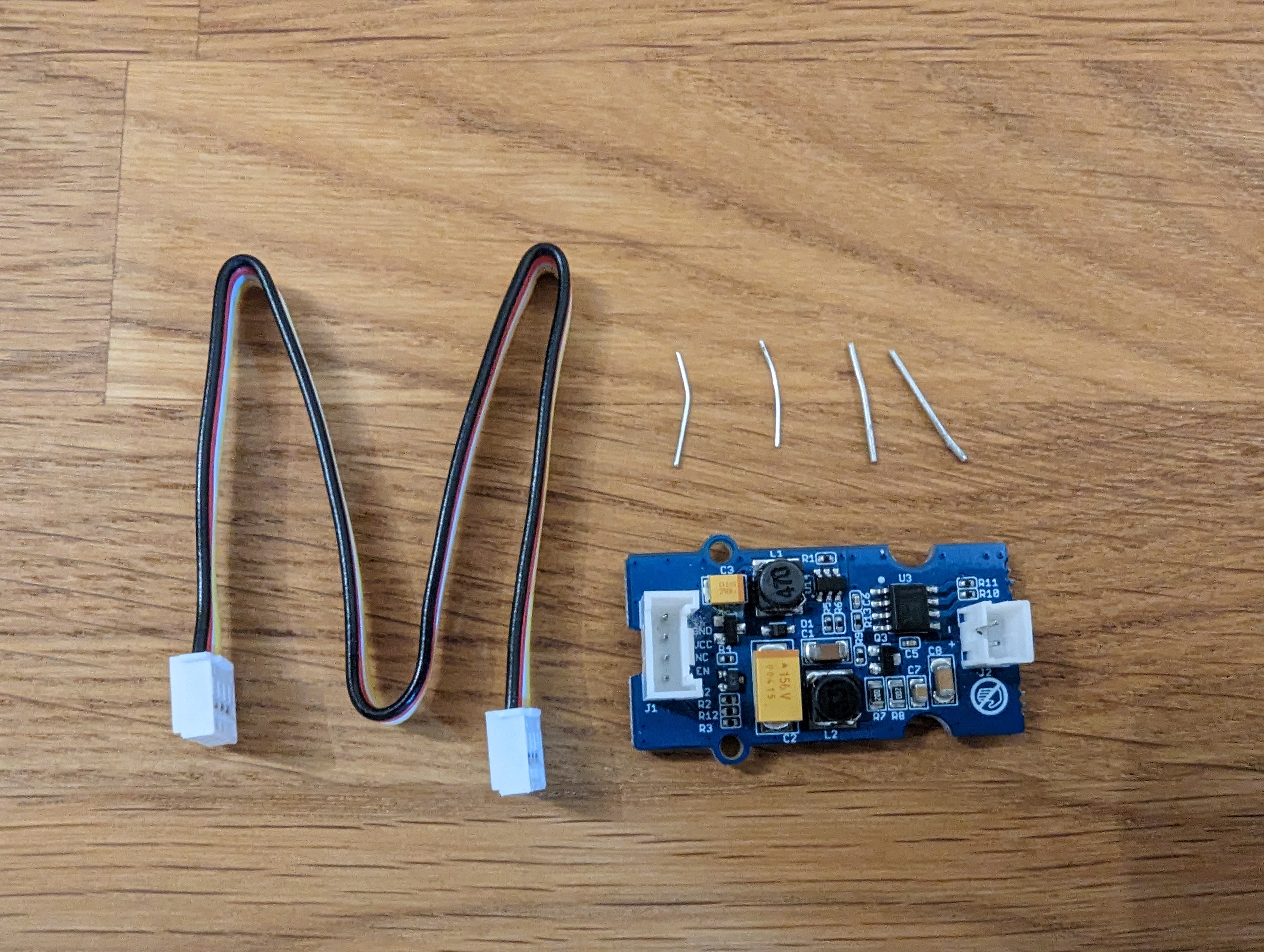
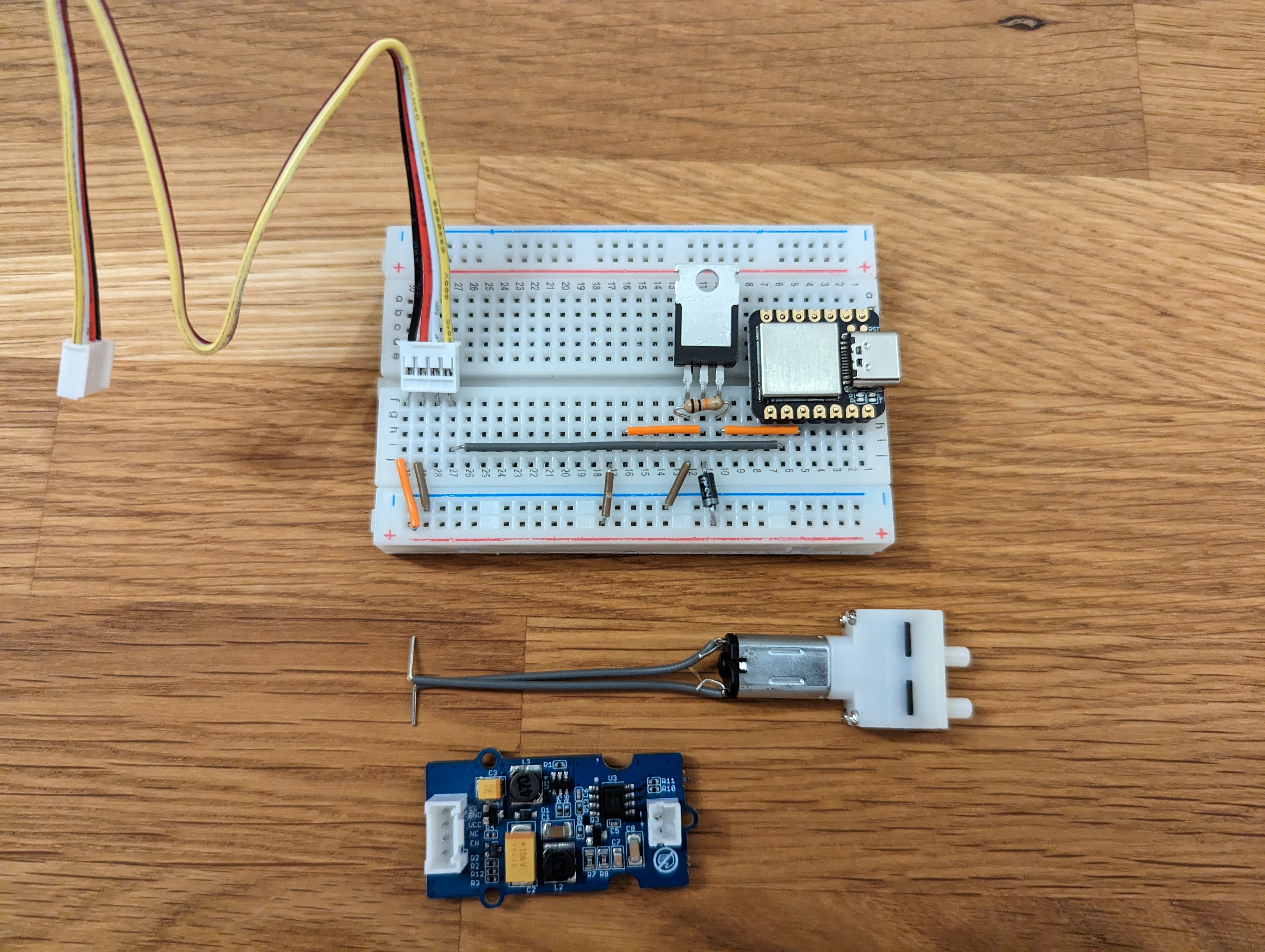
List of Components
- Breadboard (55x83 mm) (opens in a new tab)
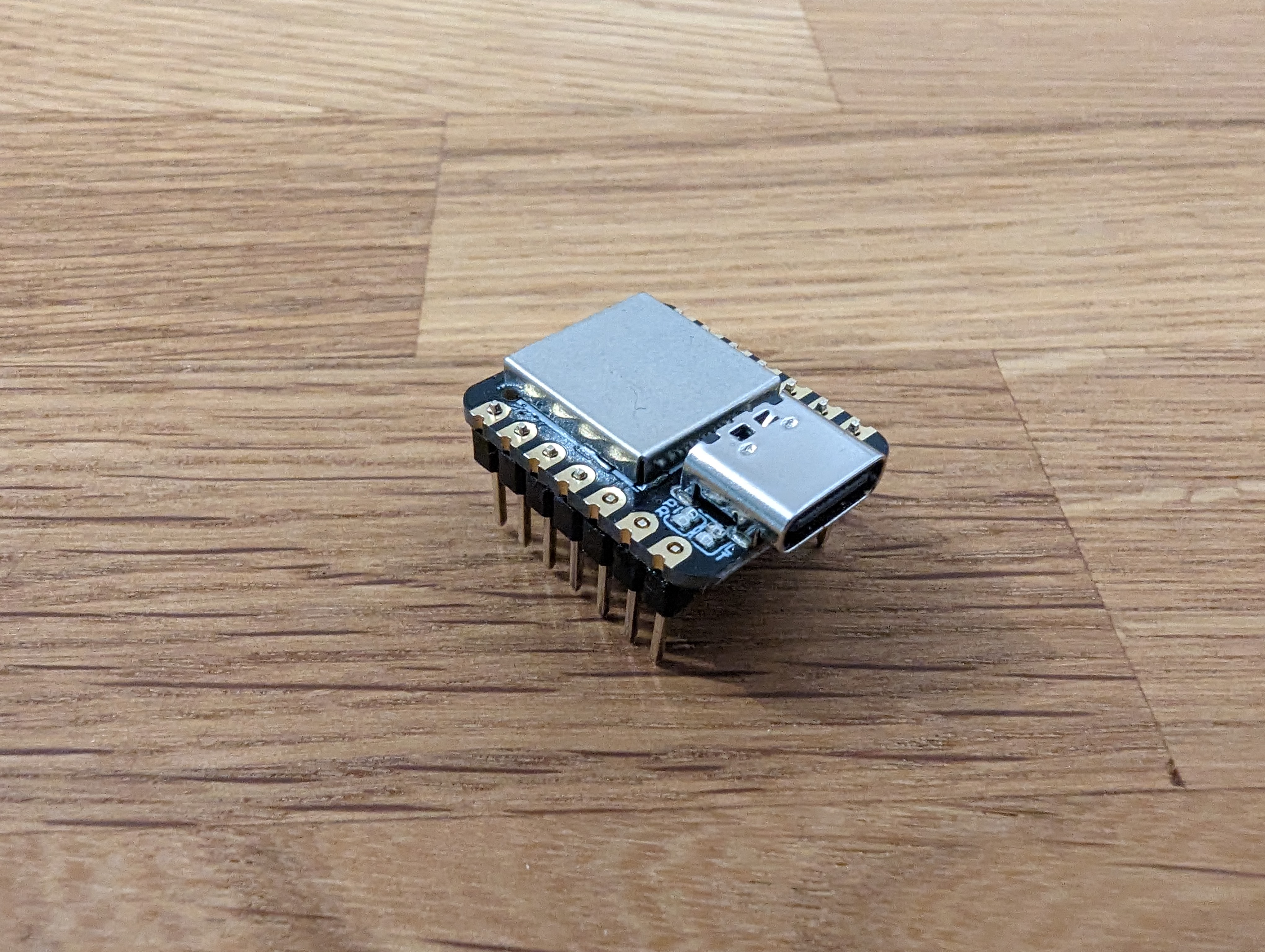
- Seeed XIAO Samd21 (opens in a new tab)
- Seeed Water Atomizer (opens in a new tab)
- M20 Mini Water Pump (opens in a new tab)
- Mosfet (IRFZ44N) (opens in a new tab)
- 10k Ohm Resistor (opens in a new tab)
- Diode (opens in a new tab)
- Jumper Wires (opens in a new tab)
- Cotton Sticks (opens in a new tab)
- 3x4 mm silicone tube (opens in a new tab), length depending on your towers height
Code
First, you need to install CicuitPython onto the Seeed XIAO (opens in a new tab).
Afterwards, create a file named code.py in the root folder of the device and add the following code:
import time
import board
from digitalio import DigitalInOut, Direction

led = DigitalInOut(board.LED_INVERTED)
led.direction = Direction.OUTPUT

pump = DigitalInOut(board.D9)
pump.direction = Direction.OUTPUT
pump_pause = 6*60
pump_interval = 2
pulse_intensity = 0.002

atomizer = DigitalInOut(board.D8)
atomizer.direction = Direction.OUTPUT
fog_interval = 60
fog_pause = fog_interval + 60 * 3

signal_interval = 10
signal_length = 0.4

delays = dict()
workers = dict()

def set_interval(delay, callback, key):
    def execute():
        if delays.get(key, 0) <= time.monotonic():
            callback()
            delays[key] = time.monotonic() + delay

    workers[key] = execute


def set_timeout(delay, callback, key):
    delays[key] = time.monotonic() + delay

    def execute():
        if not key in delays.keys():
            return
        if delays[key] <= time.monotonic():
            callback()
            del delays[key]

    workers[key] = execute


def turn_pump_on_by_pwm(duration=pump_interval, pulse=pulse_intensity):
    led.value = False
    t_end = time.monotonic() + duration
    while time.monotonic() < t_end:
        pump.value = True
        time.sleep(pulse)
        pump.value = False
        time.sleep(pulse)
    led.value = True


def turn_atomizer_off():
    atomizer.value = False


def turn_atomizer_on(duration=fog_interval):
    atomizer.value = True
    set_timeout(duration, turn_atomizer_off, 'FOG_OFF')

def send_signal_to_powerbank():
    if not atomizer.value:
        turn_atomizer_on(signal_length)

set_interval(pump_pause, turn_pump_on_by_pwm, 'PUMP_ON')
set_interval(fog_pause, turn_atomizer_on, 'FOG_ON')
set_interval(signal_interval, send_signal_to_powerbank, 'SIGNAL')
turn_pump_on_by_pwm(10)

while True:
    for execute in workers.values():
        execute()
Assembly
Once you have loaded the code onto the XIAO you can assemble the circuitry.
This does not mean, that you cannot modify the code afterwards, it is just easier to start off this way.
If you know what you are doing, you can jump ahead to the circuit reference
Seeed XIAO
Connect the Seeed XIAO microcontroller to the pin headers found in the packaging. You can optionally solder them to ensure better hold.
Take the breadboard and place it so you look at it with the red line pointing torwards you. Put the microcontroller on the right side, facing the USB c port outwards.
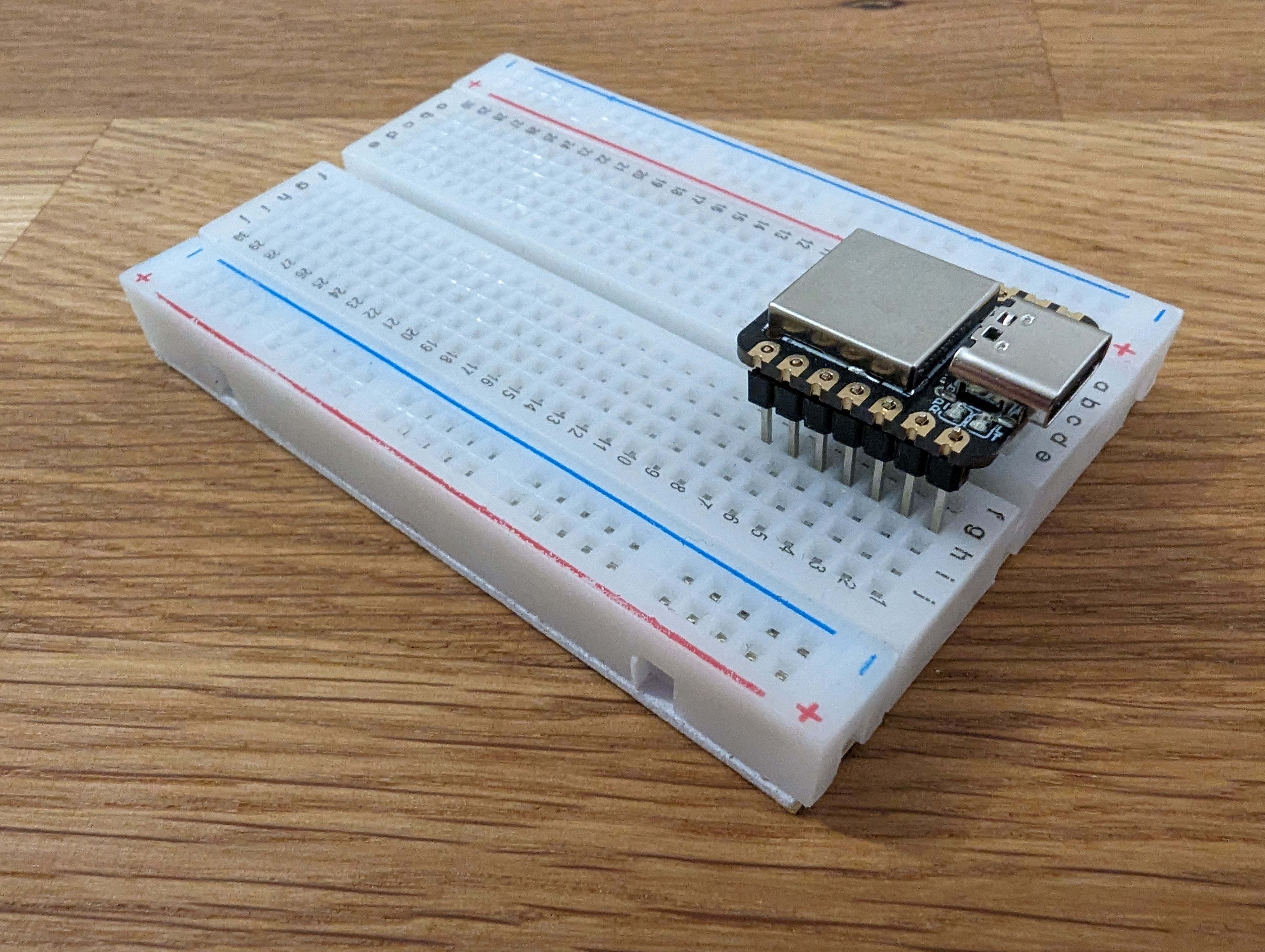
Then, connect the 5 volt and ground pins to the power and ground rails of the breadboard.
During picture taking an error happened:
These two wires are not present on the following picutures, because it was not noticed early enough that they are missing.
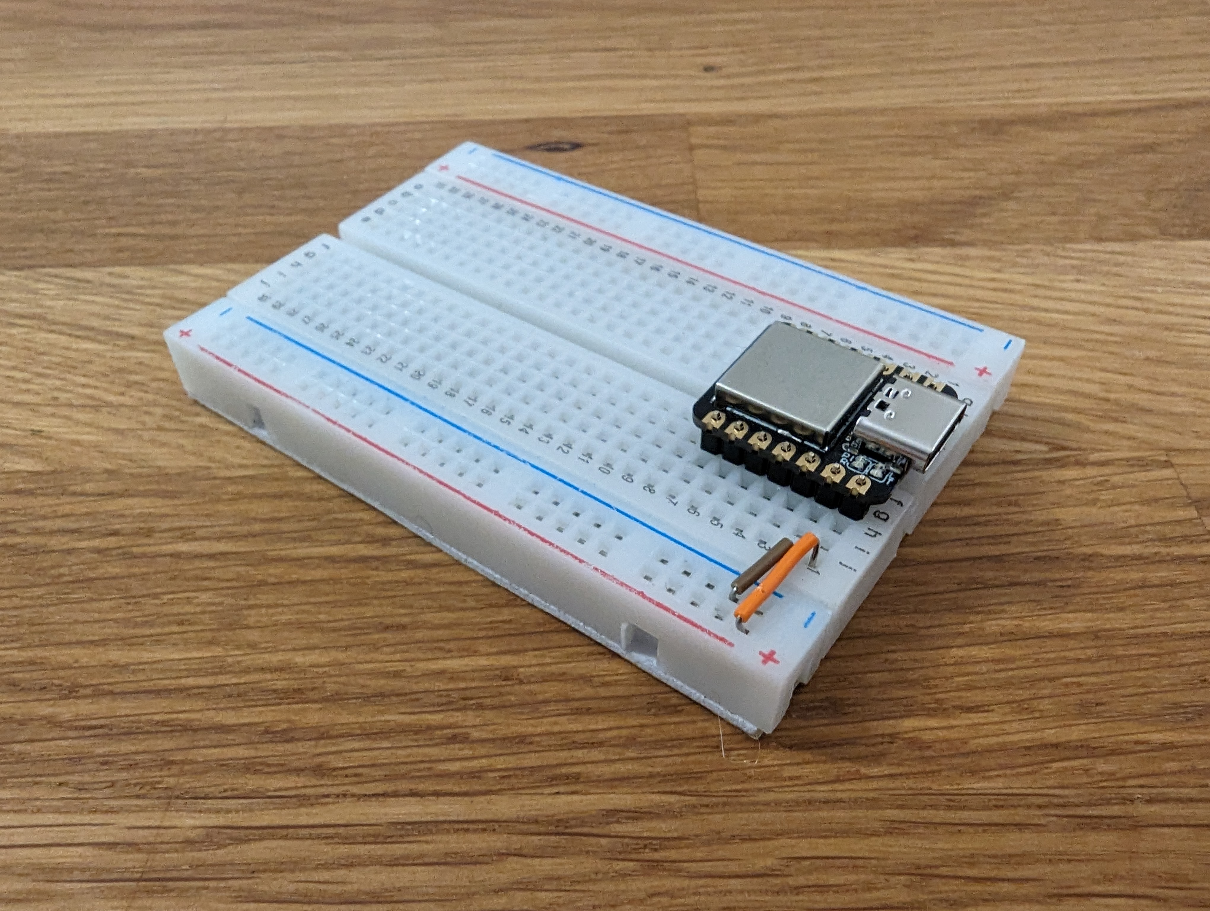
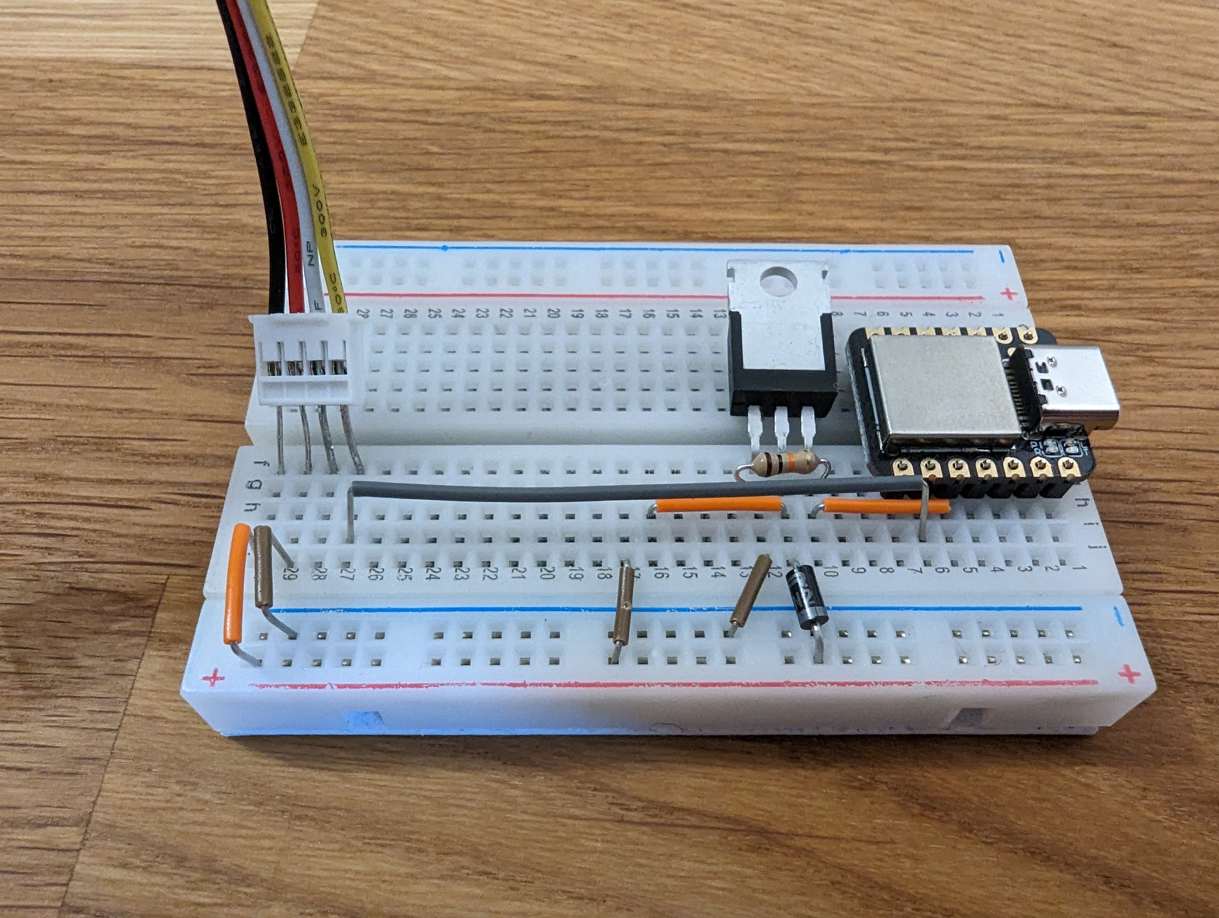
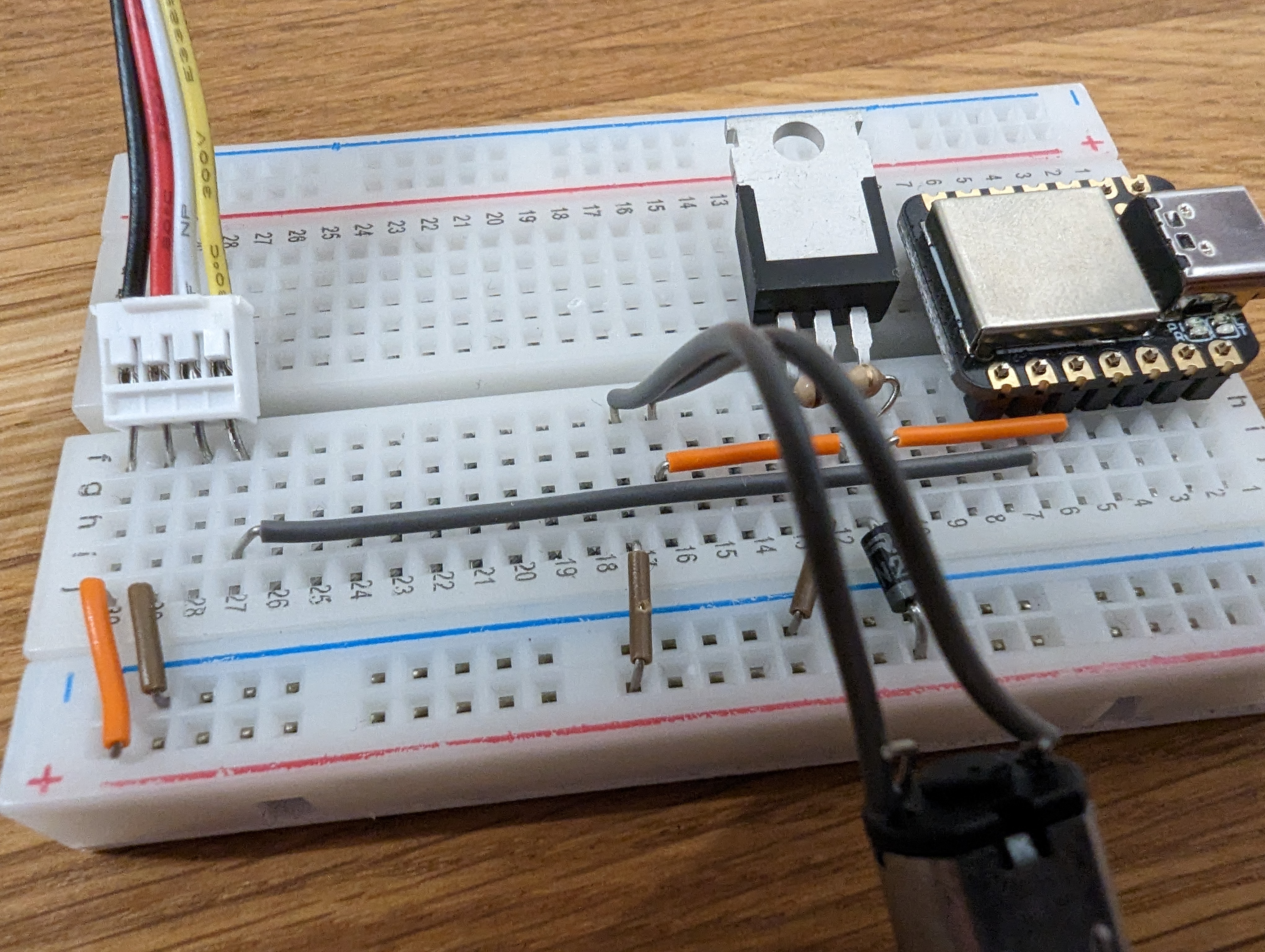
Pump (Preparation)
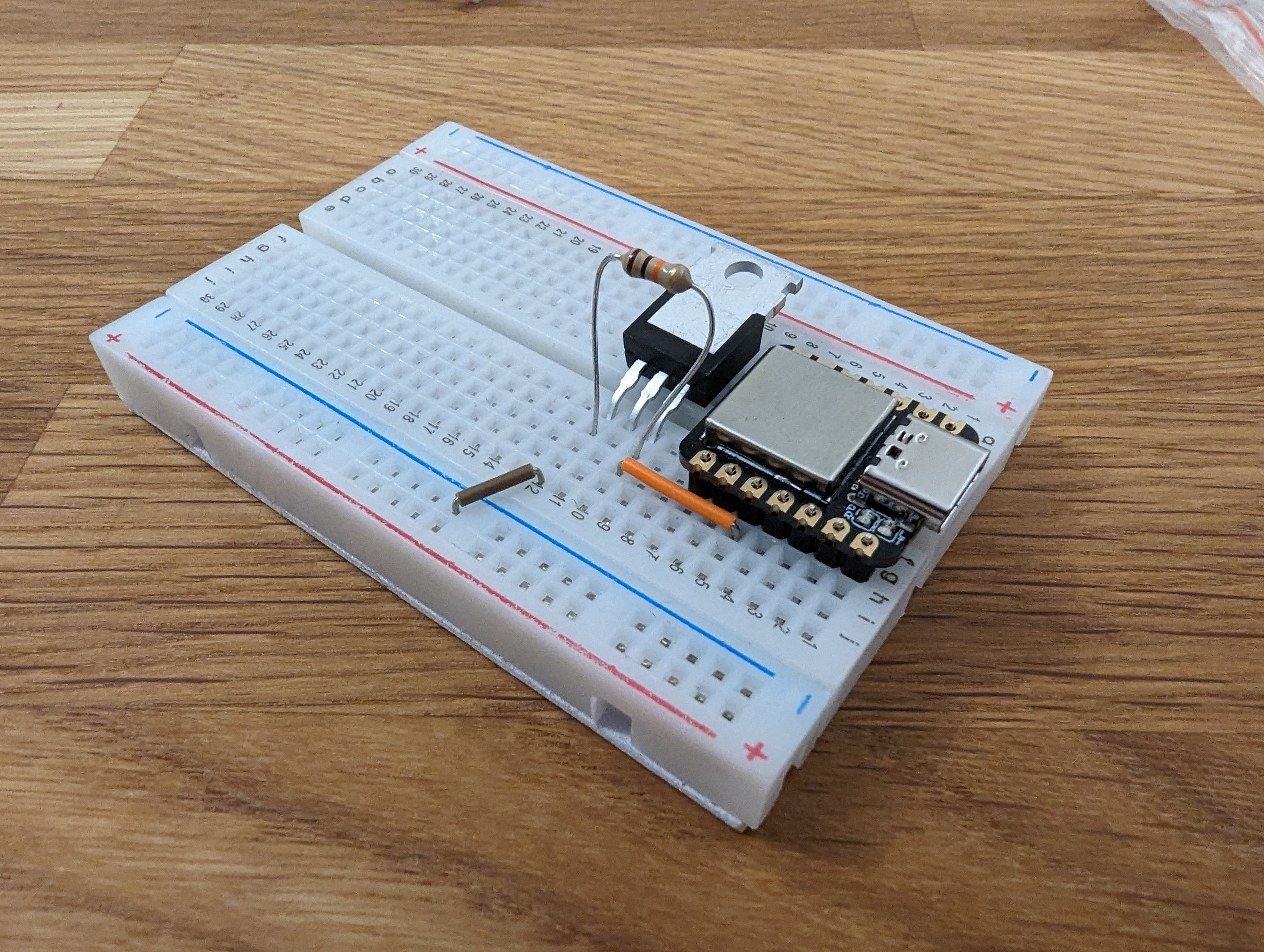
Now get a transistor (IRFZ44N) and two jumper wires. Connect the first jumper wire with the third pin from the left of the xiao (pin 9 (opens in a new tab)). Put the transistor into place, such that the right pin of it connects to the other end of the first jumper wire. Then, connect the left pin of the transistor to ground.
Pay attention to the orientation of the transistor.
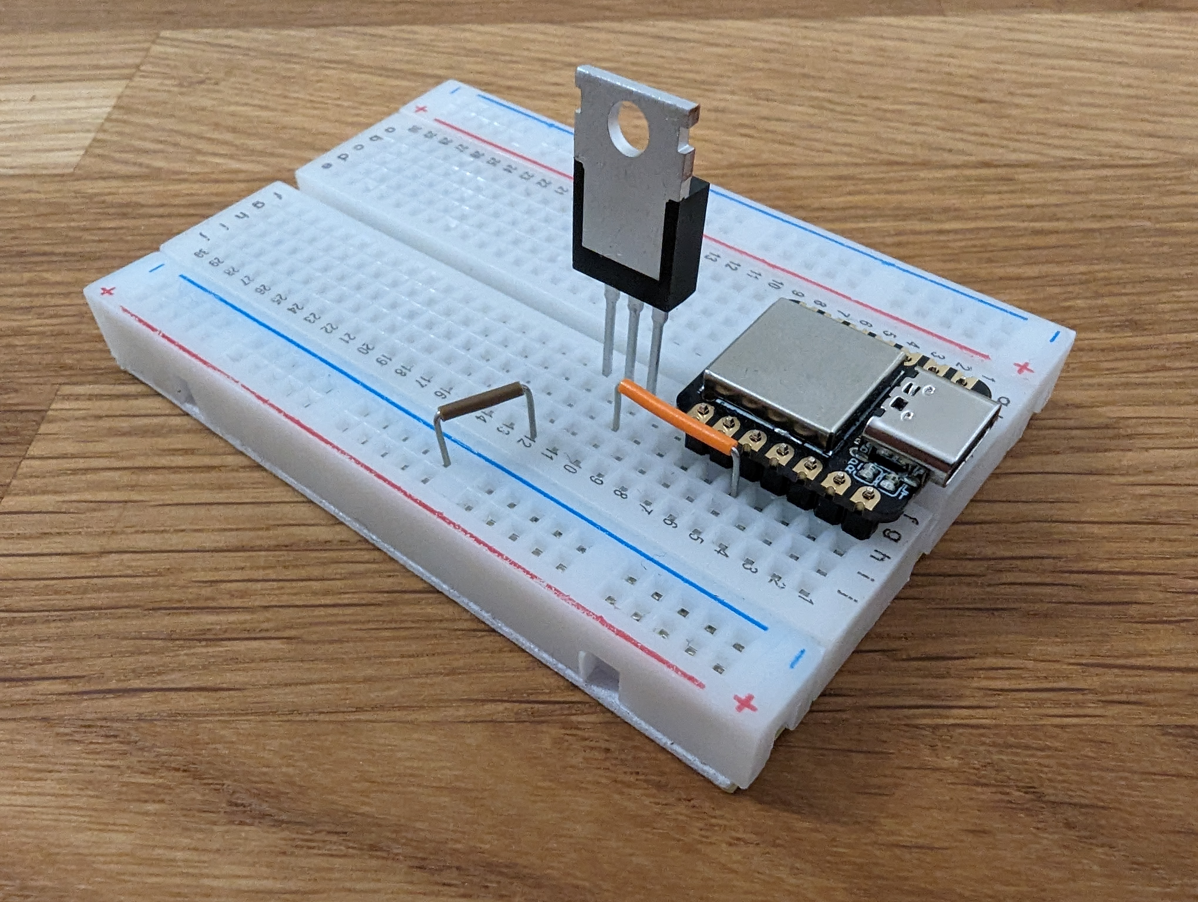
You can bend the transistor over to get it out of the way. Next, add the 10k Ohm resistor connecting the outer pins of the transistor. This is needed to let the transistor be turned off by the microcontroller properly.
Trim the resistors wires and keep the cutoffs. Then add the flyback diode (opens in a new tab), oriented like in the picture. It should be connected to the middle pin of the transistor and the power rail.
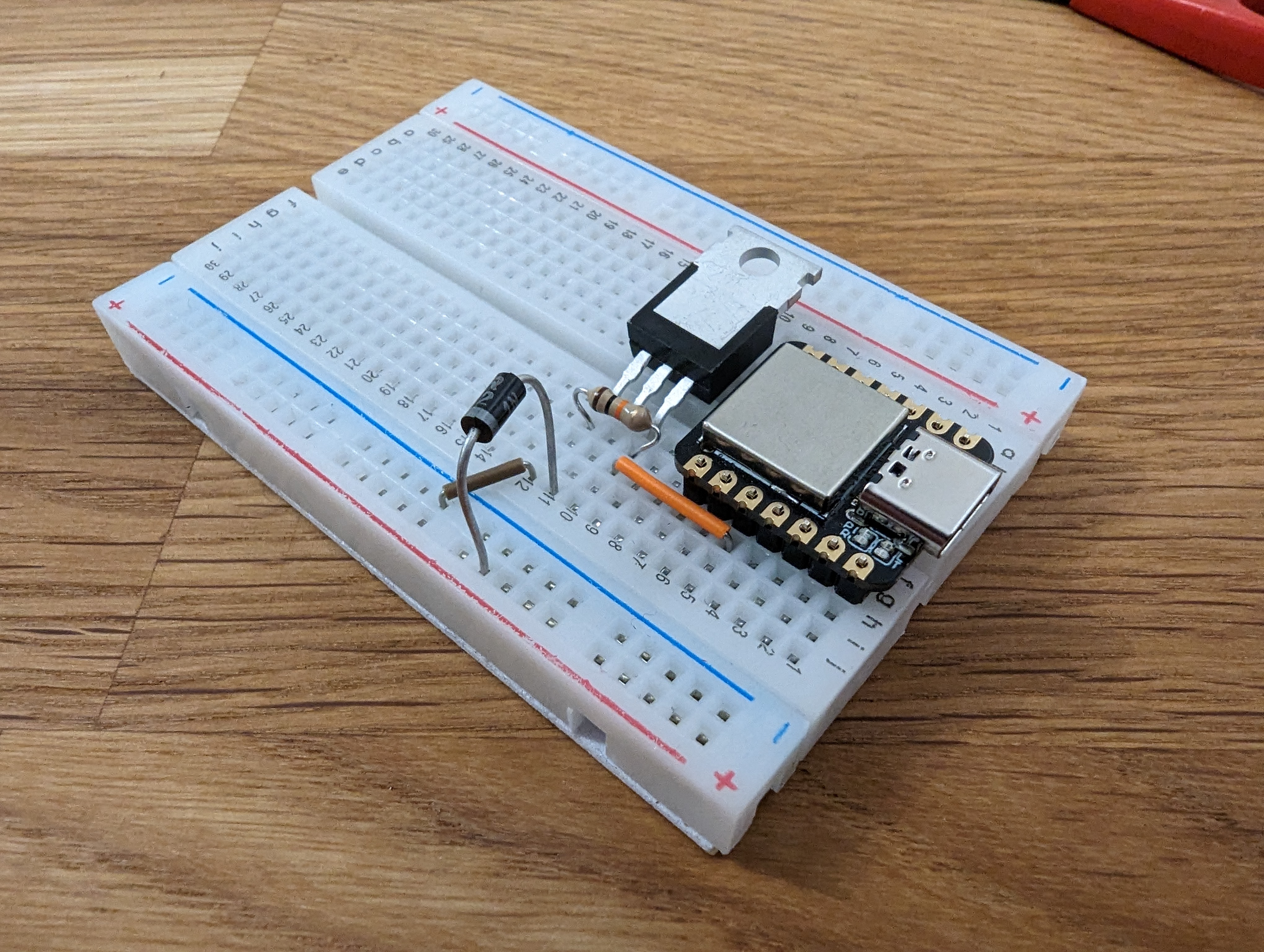
Again, cut off the excess wires and keep them for later.
Add two more jumper wires, one connecting to the middle of the transistor pin and one connecting to the power rail. Both wires should also connect to two neighbouring columns. These columns will be used to connect the pump.
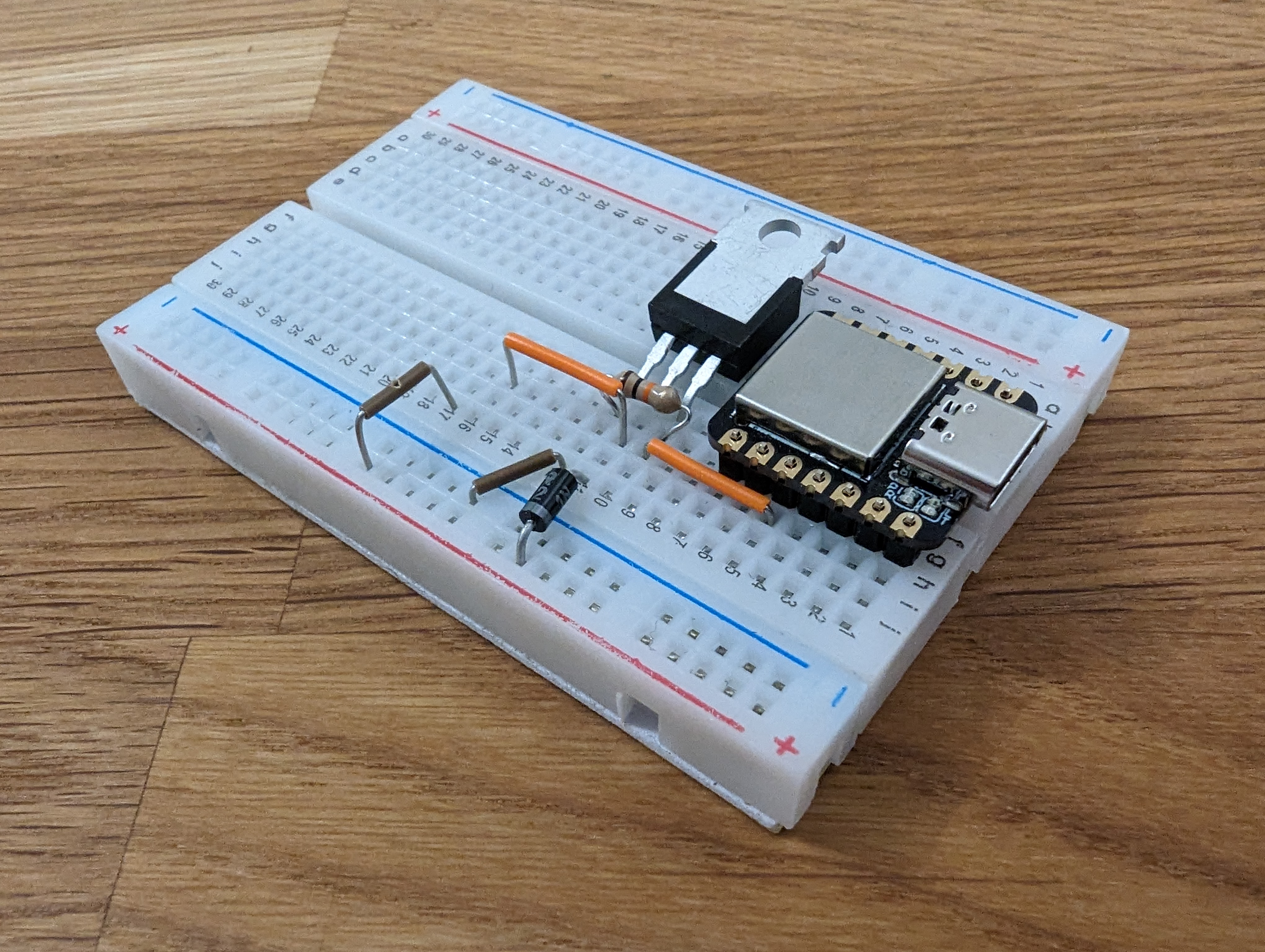
You can compare your assembly with the picture below.
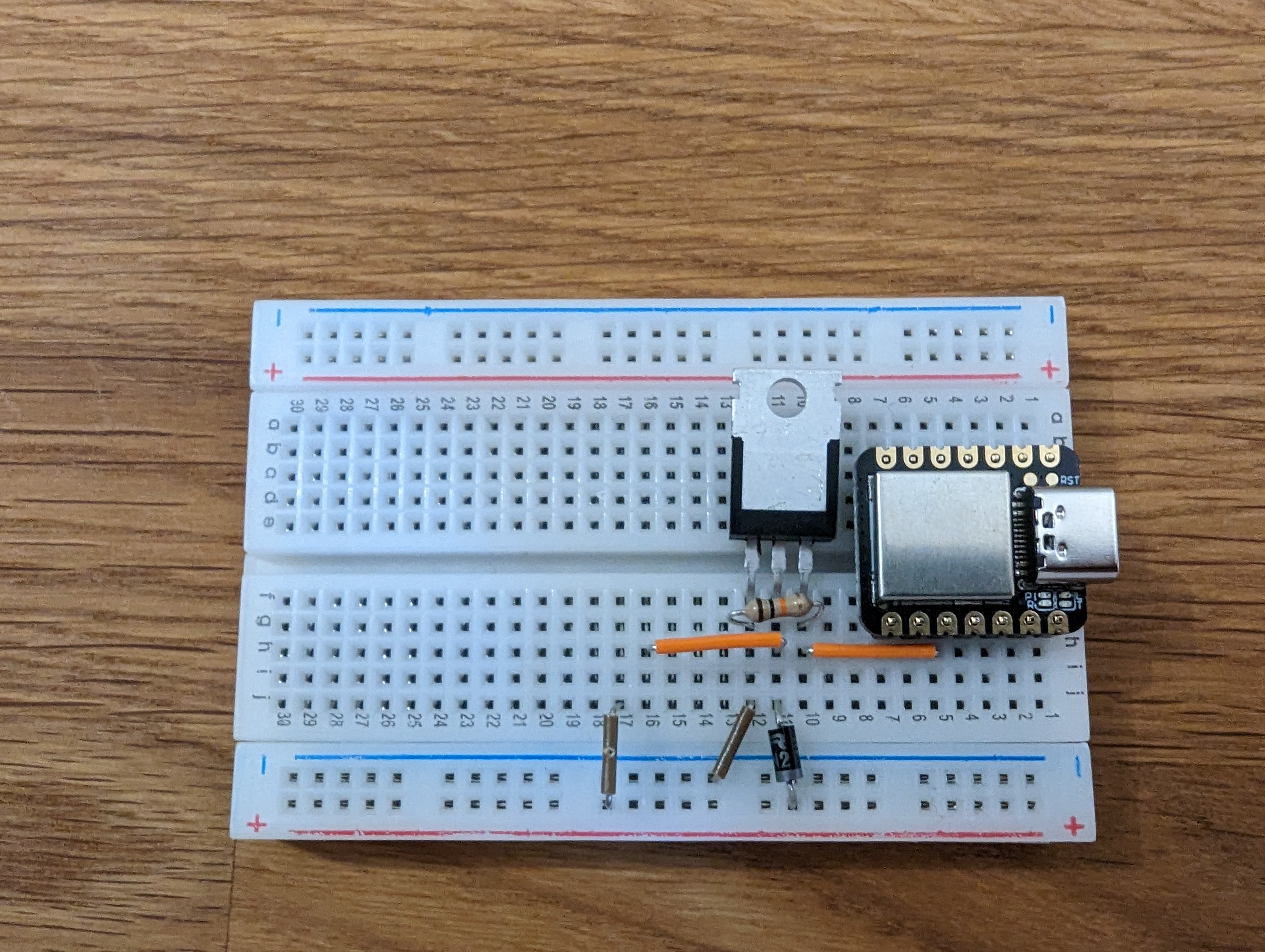
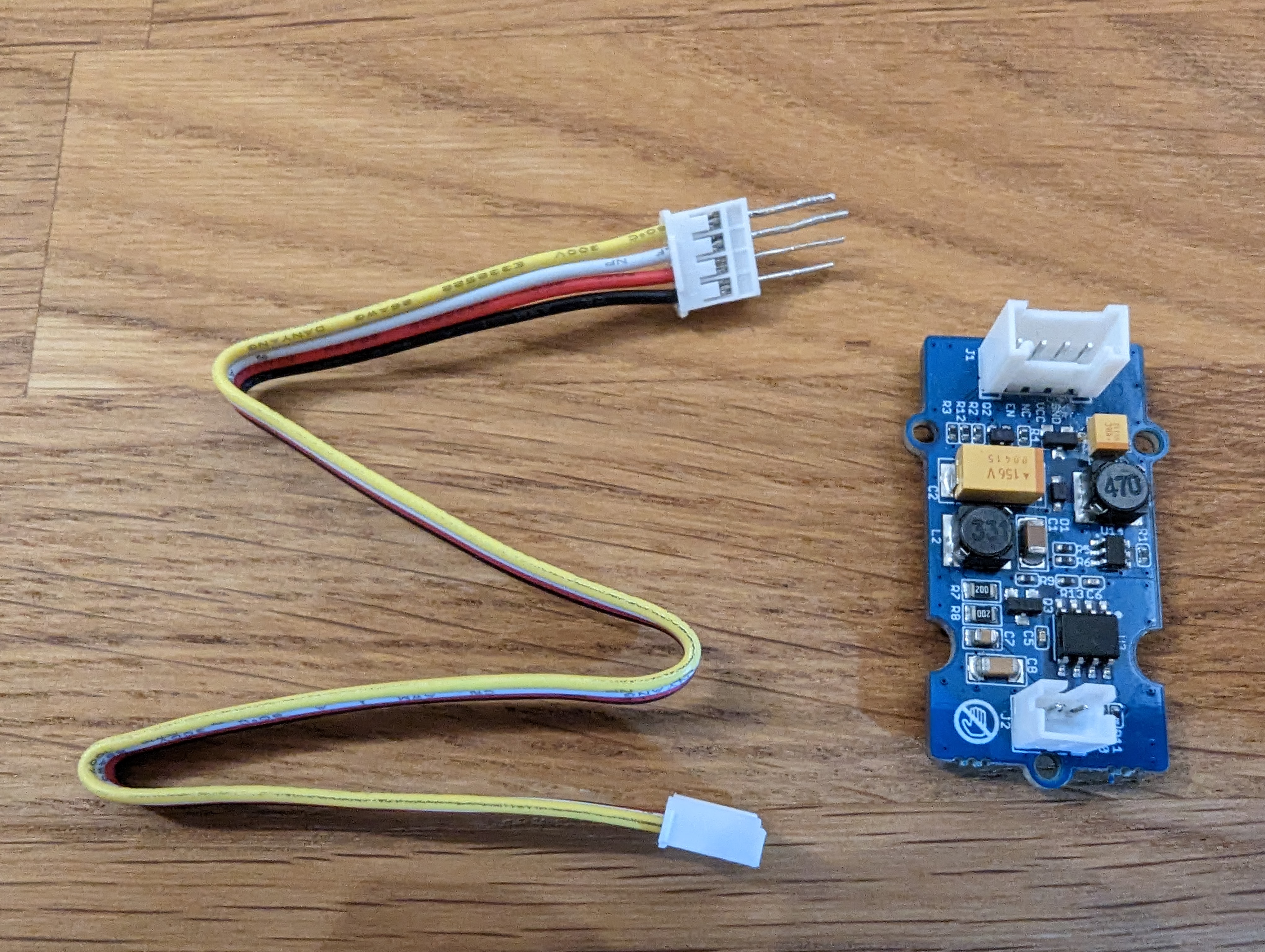
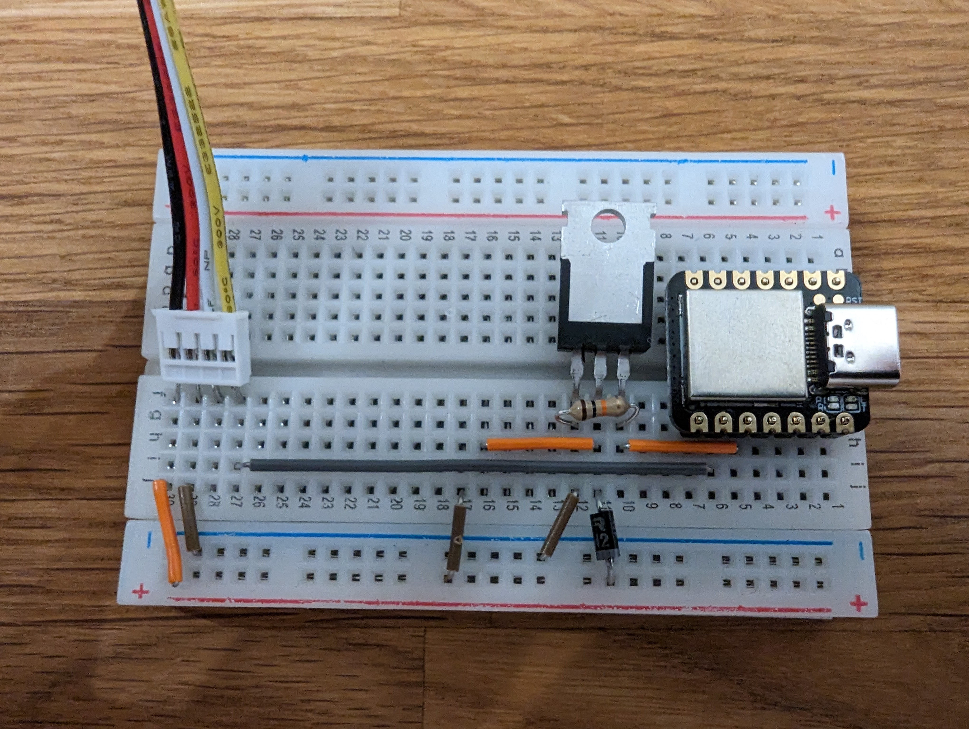
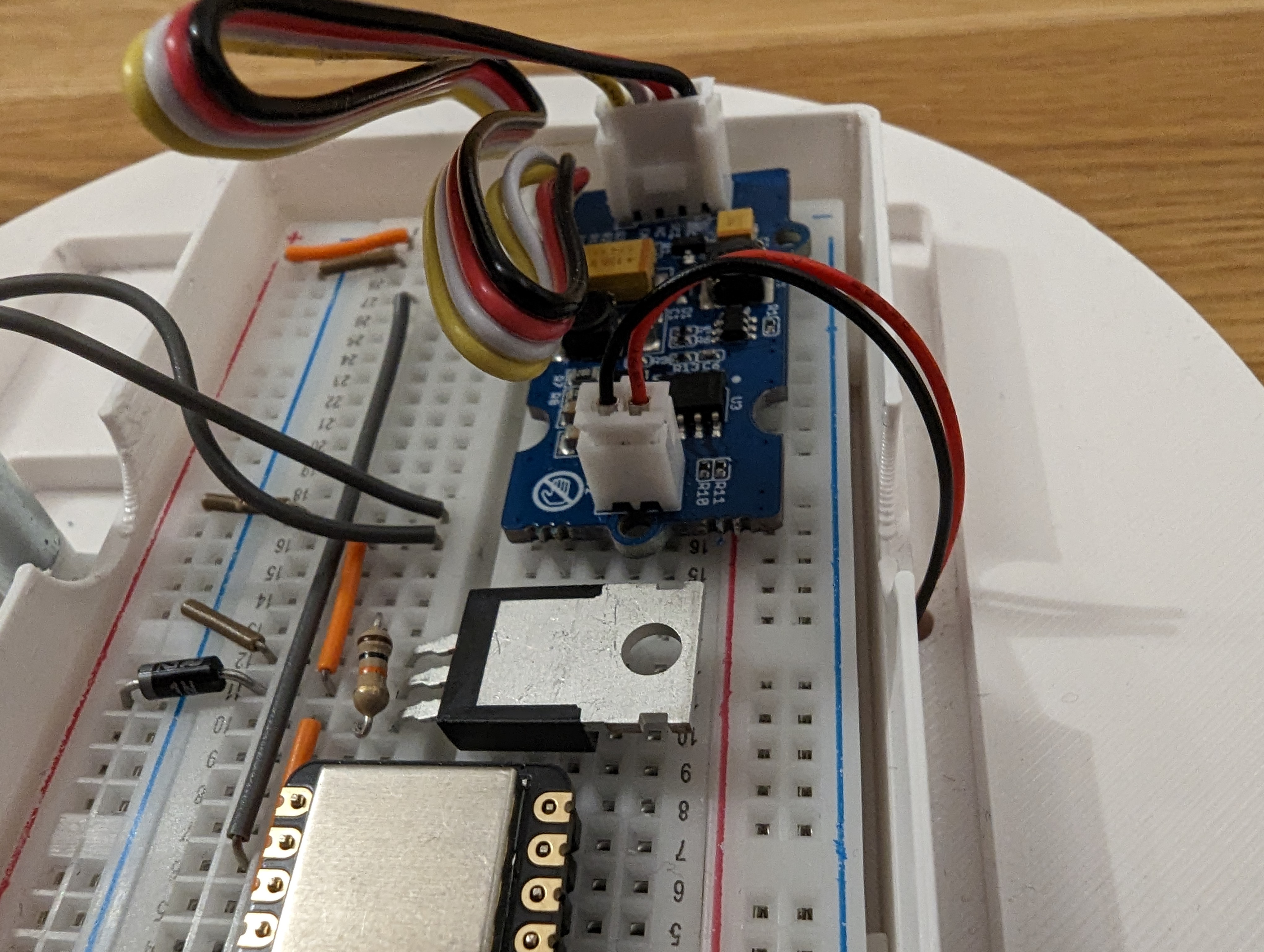
Atomizer (Preparation)
Take the cutoffs, the grove connector cable and the seeed water atomization module.
Plug the wires into one end of the connector cable. These are used to stick the cable into the breadboard.
Put the prepared grove cable on the left side of the breadboard. Connect the yellow cable to pin 8 (opens in a new tab). Then connect the red and black cable to power and ground rails.
During picture taking an error happened:
The left most cables connecting power and ground are reversed.
Again, you can compare your board to the picture below.
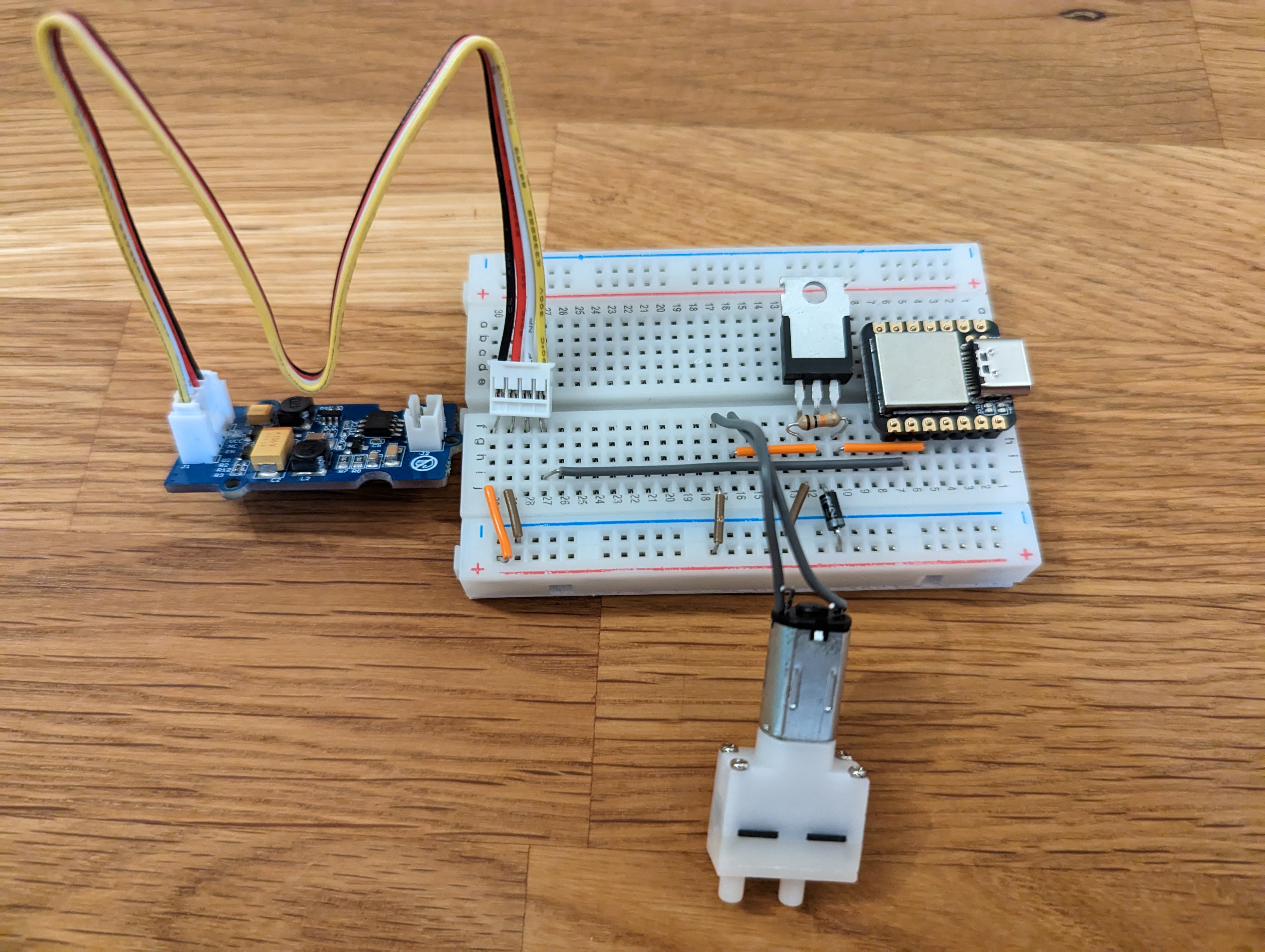
Finishing the assembly
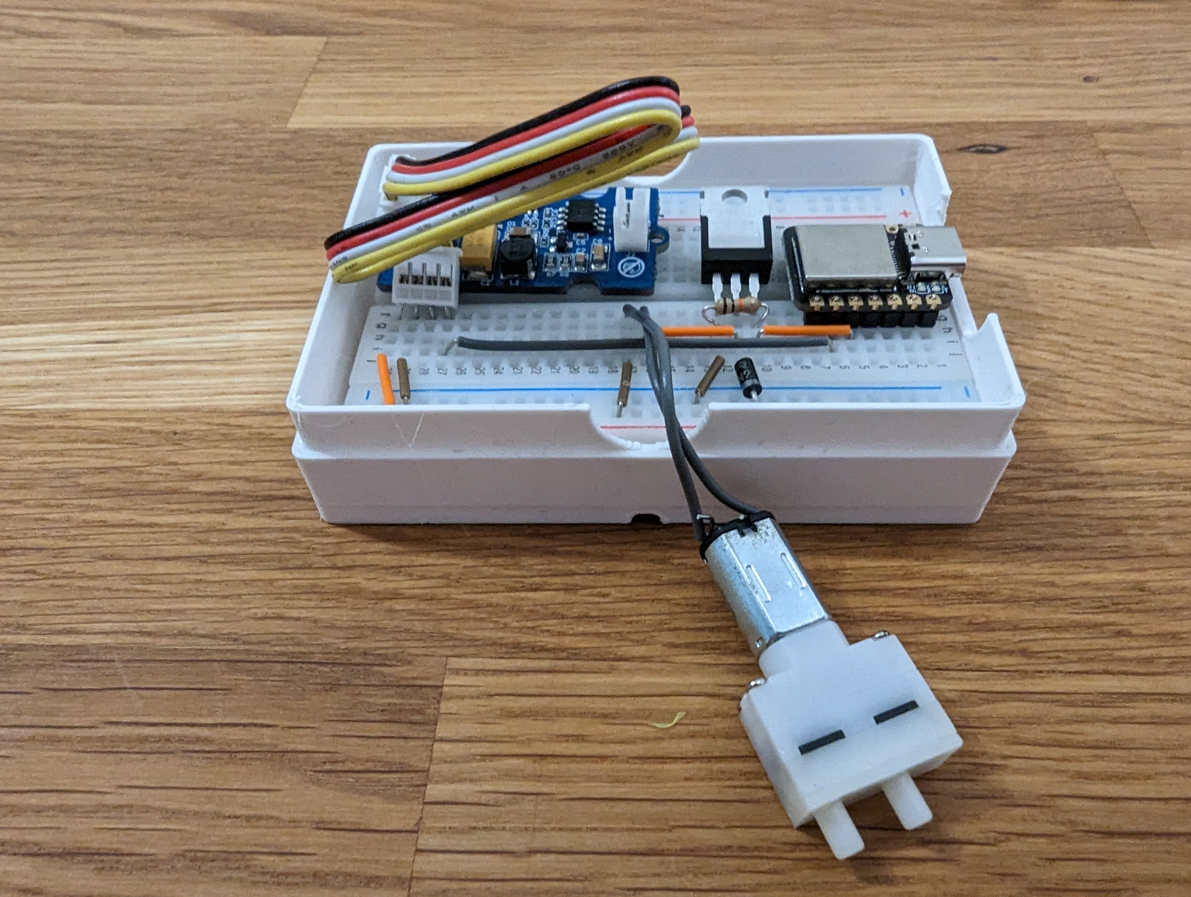
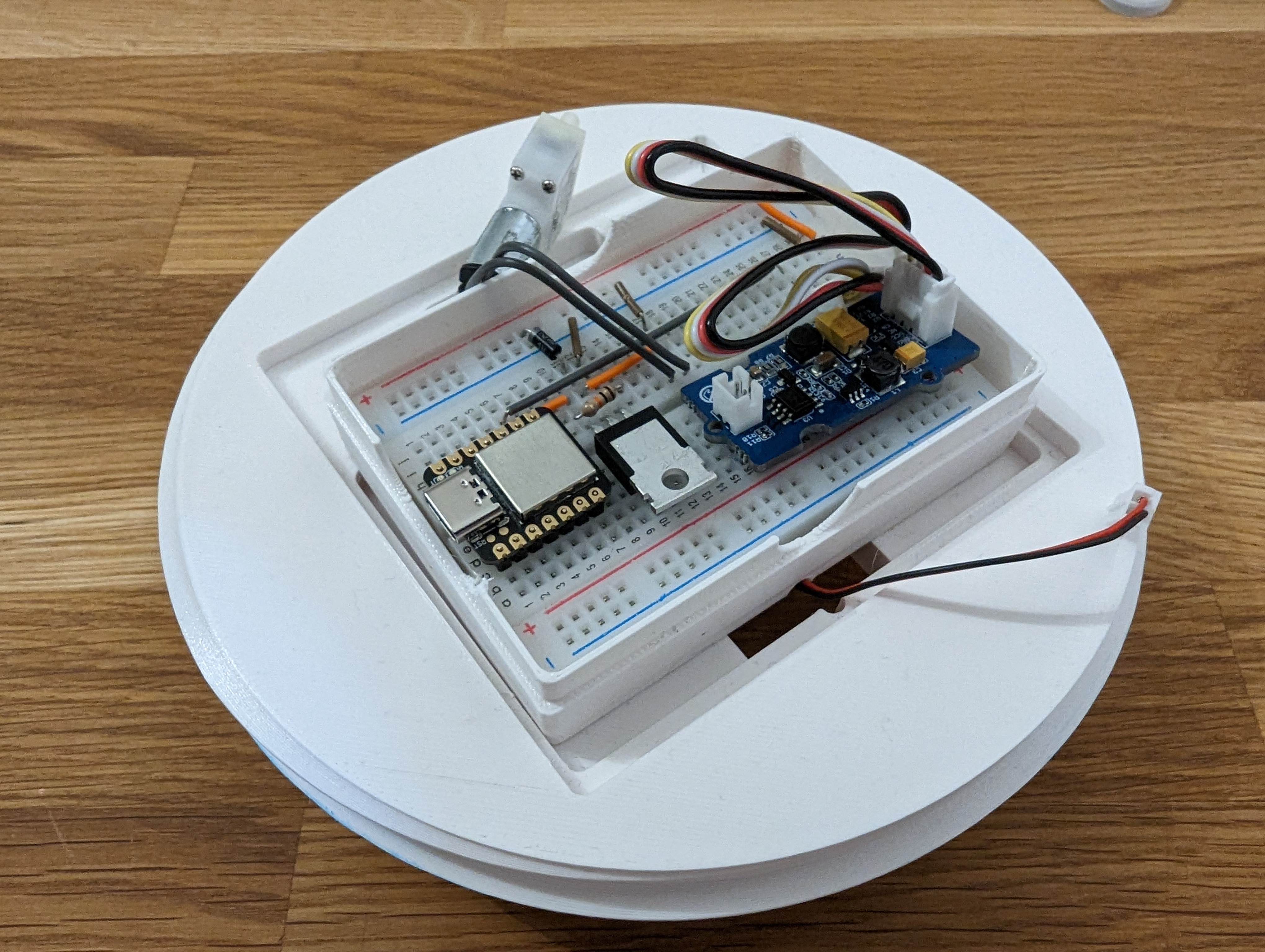
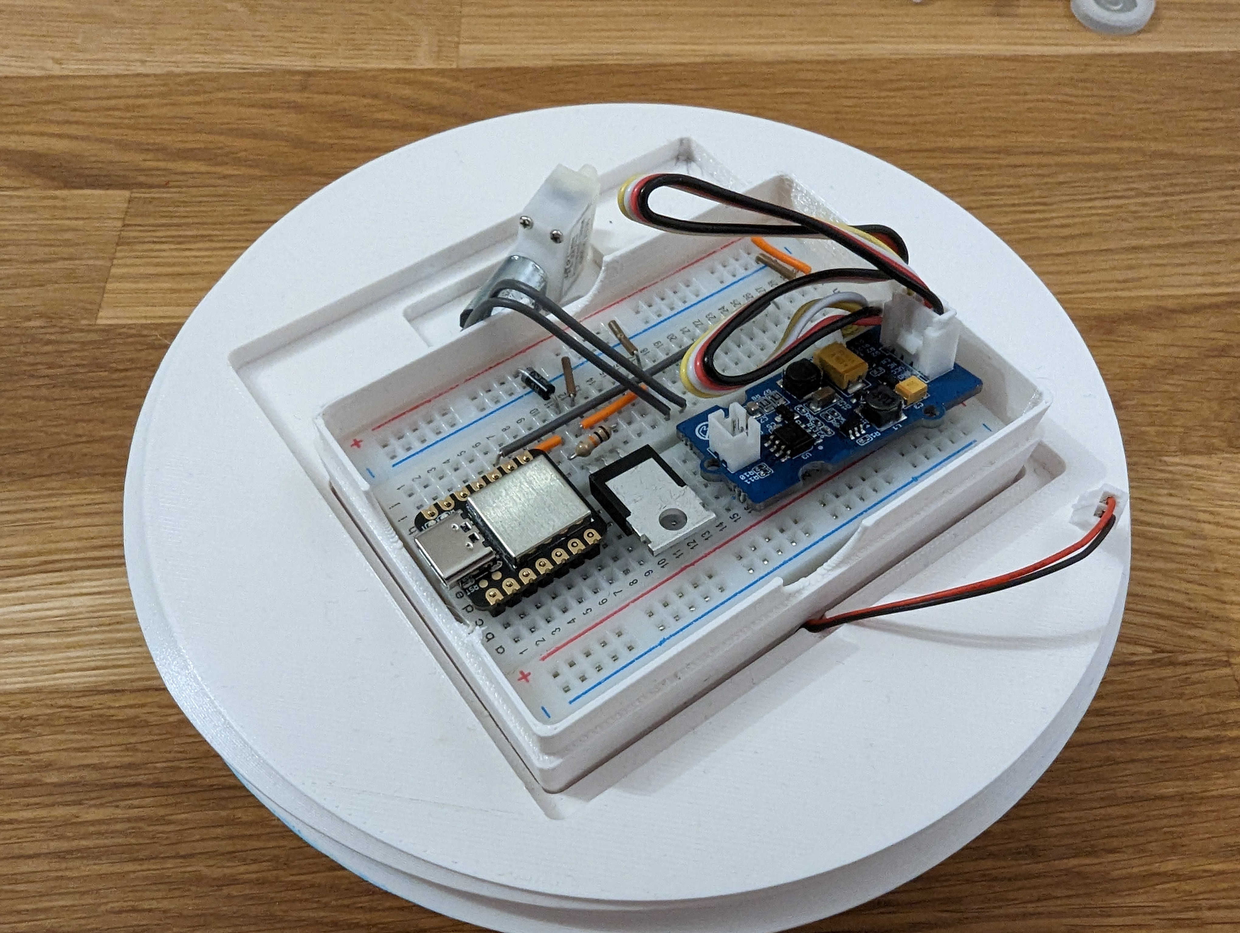
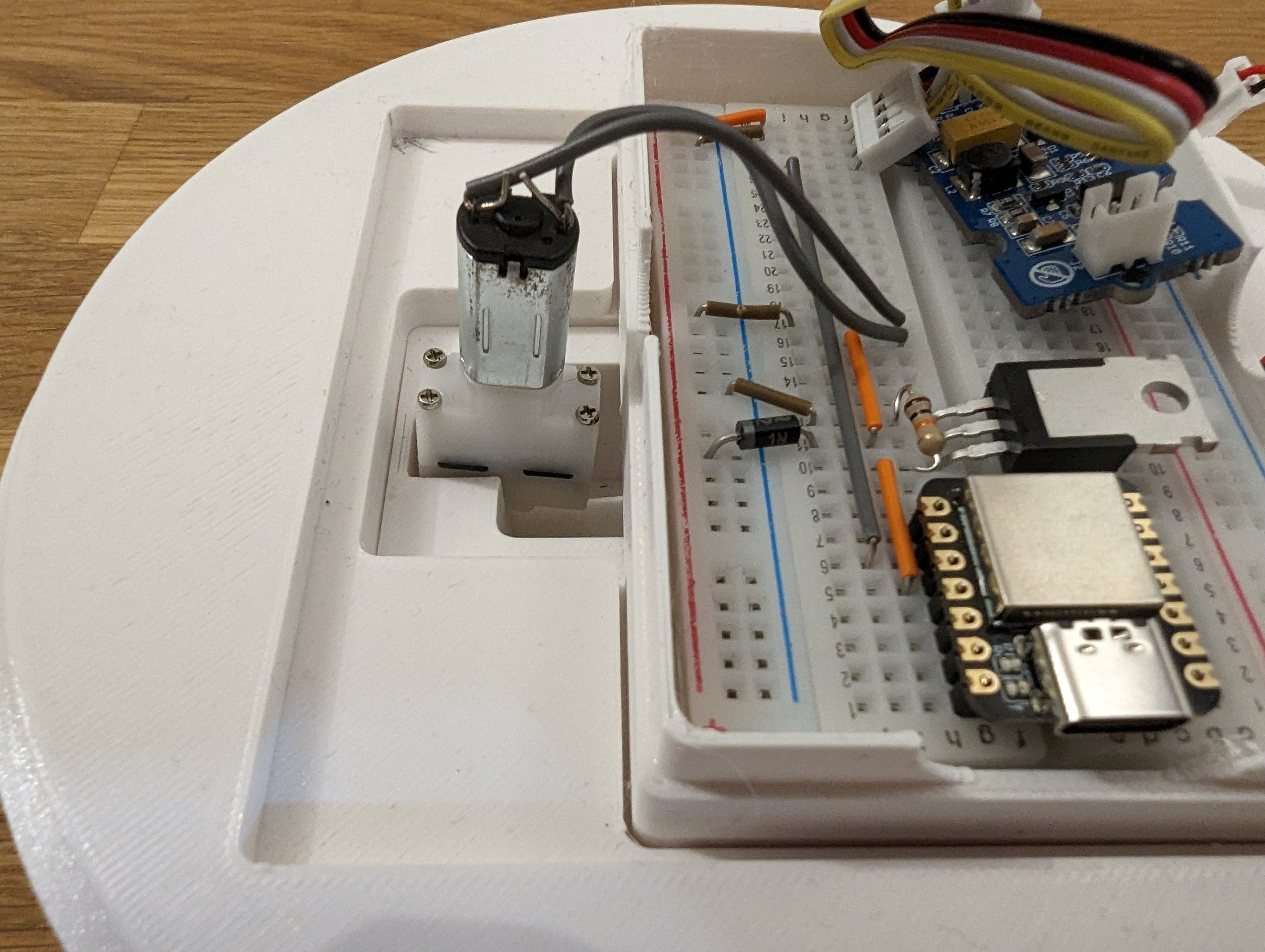
Now, take the prepared breadboard, the atomizer module and the pump with two jumper wires.
Connect the jumper wires to the pump of the pins. You do not need to solder them, it is sufficient to bend them like in the picture below.
Be very careful with the pump, as it can easily break.
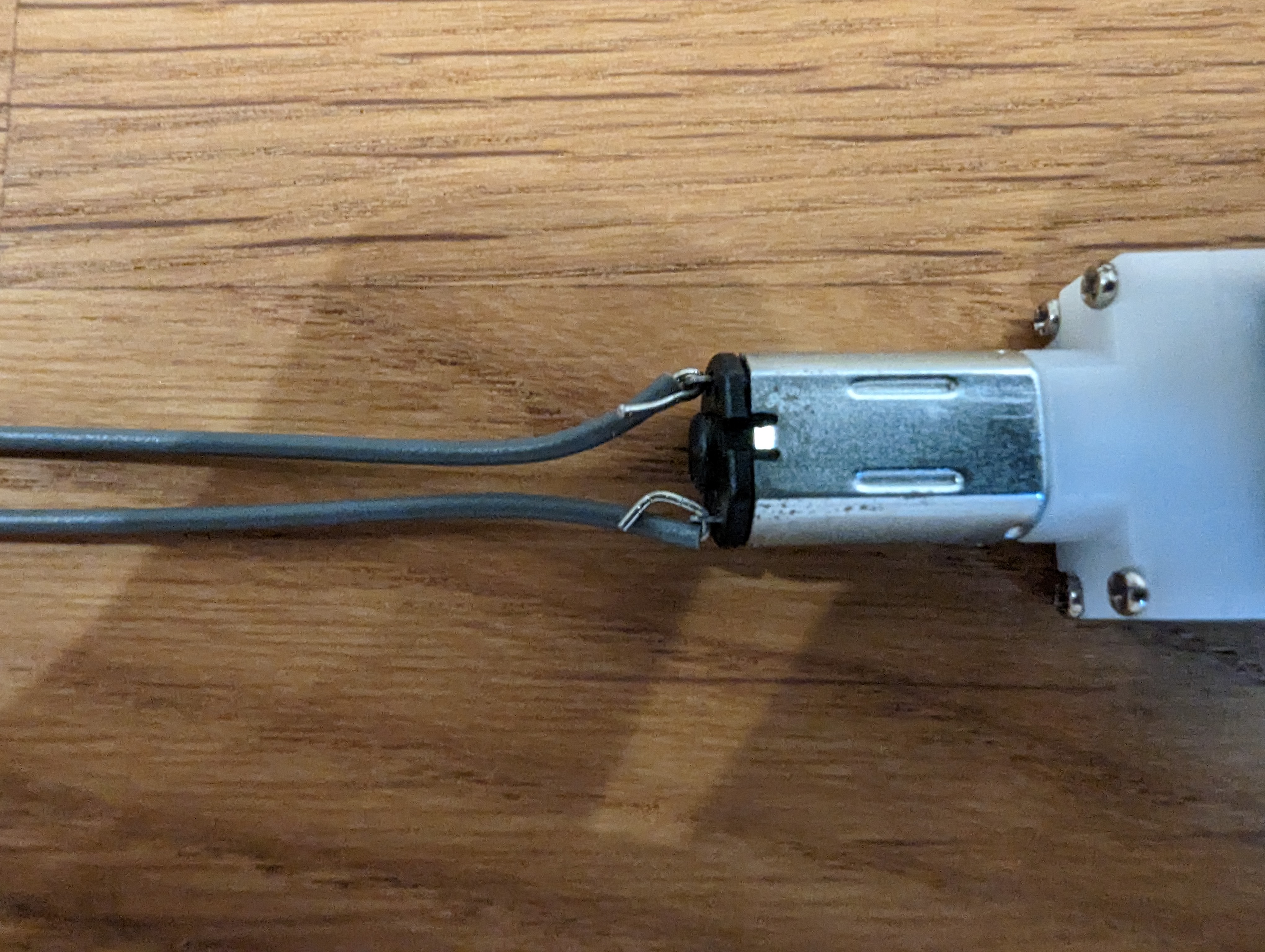
Connect the other sides of the jumper wires to the according wires like described above. It does not matter which cable is connected to ground or power.
Lastly, connect the grove cable to the grove connector on the module.
Your breadboard should look like in the picture below.
Reference
Mounting the electronics into the tower
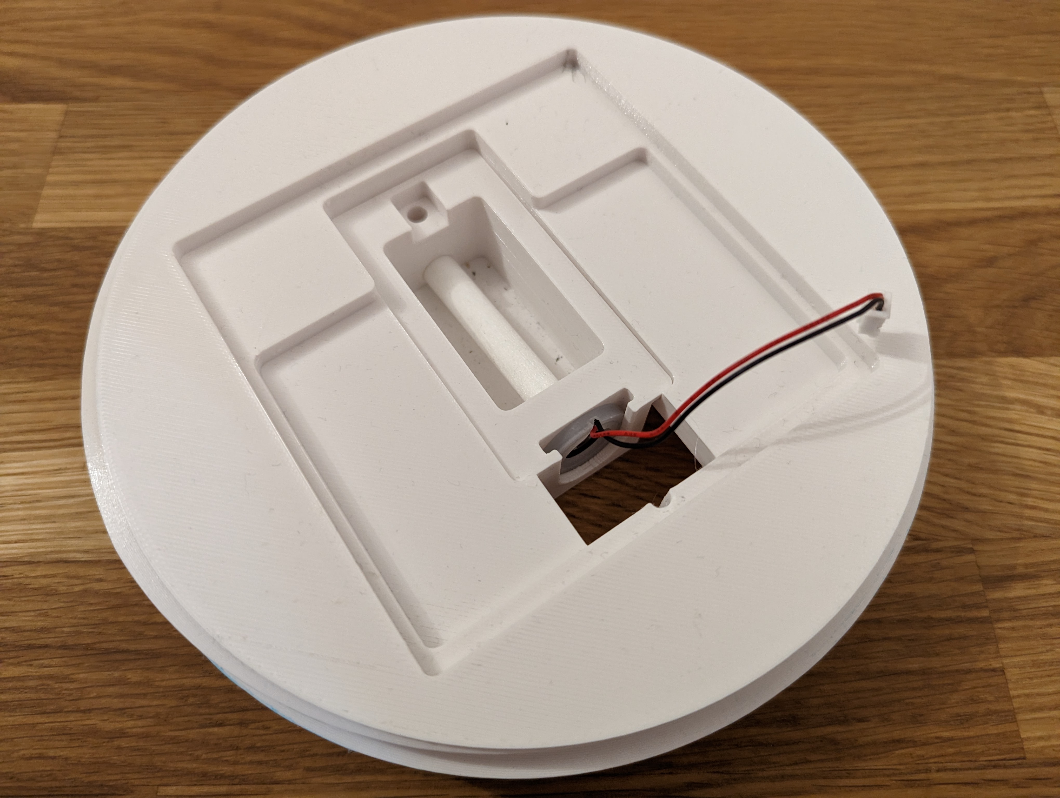
To put the circuitry to action, you first need to mount it into the tower.
Take the electronics case (opens in a new tab) and the breadboard. Lay the breadboard into the case, such that the XIAO's USB port points to the cutout on the side. You can also use the tape on the bottom of the breadboard and mount it permanently into the case.
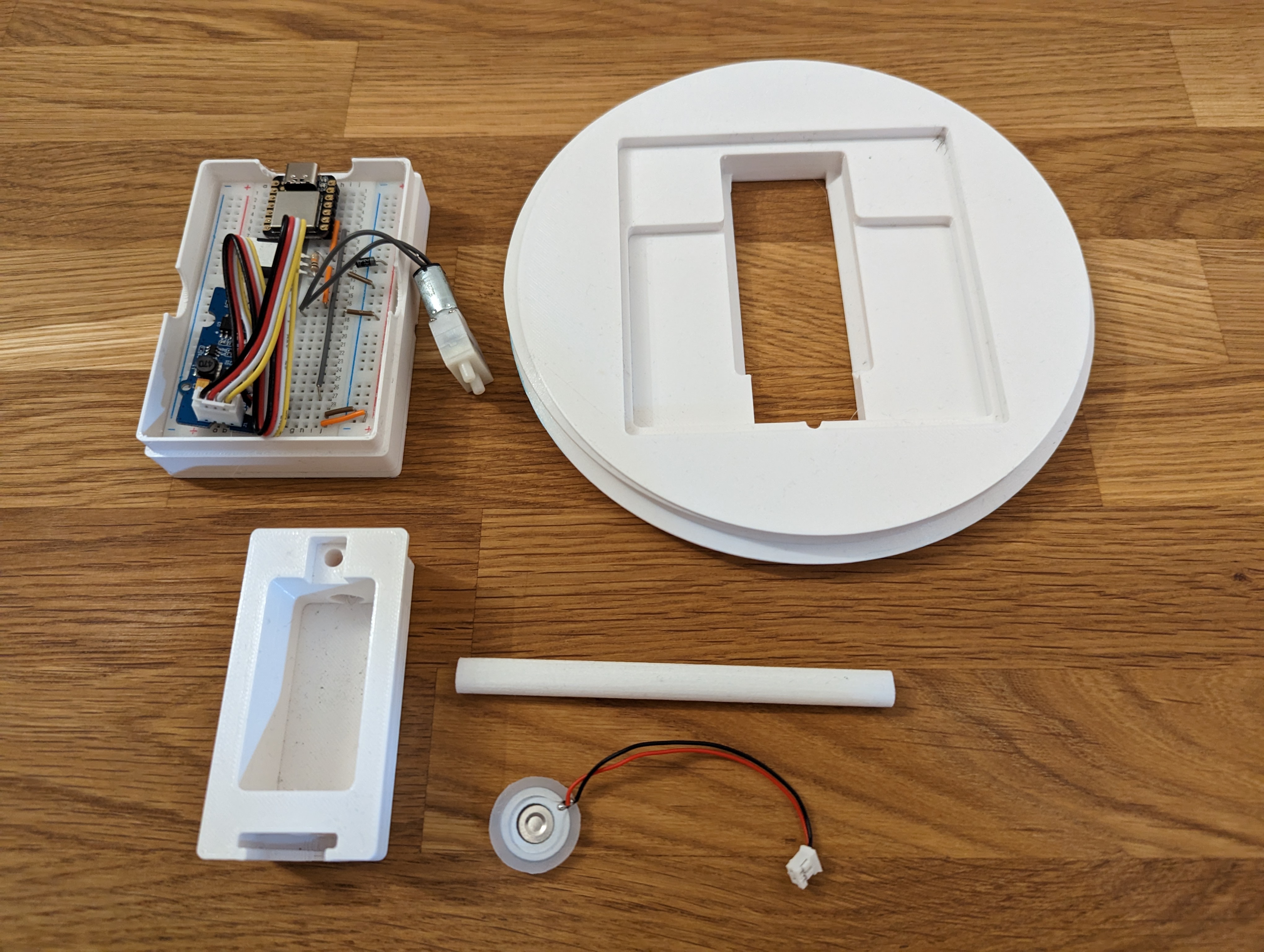
For the next step you will need:
- the electronics case (opens in a new tab) with assembled breadboard
- a cotton stick
- a piezo disk (this comes with the atomizer module)
- one head tank (opens in a new tab)
- one head mount (opens in a new tab)
slide the cotton stick through the hole of the head tank, until it touches the other end and cannot be pushed further. There is a cutout to guide you.
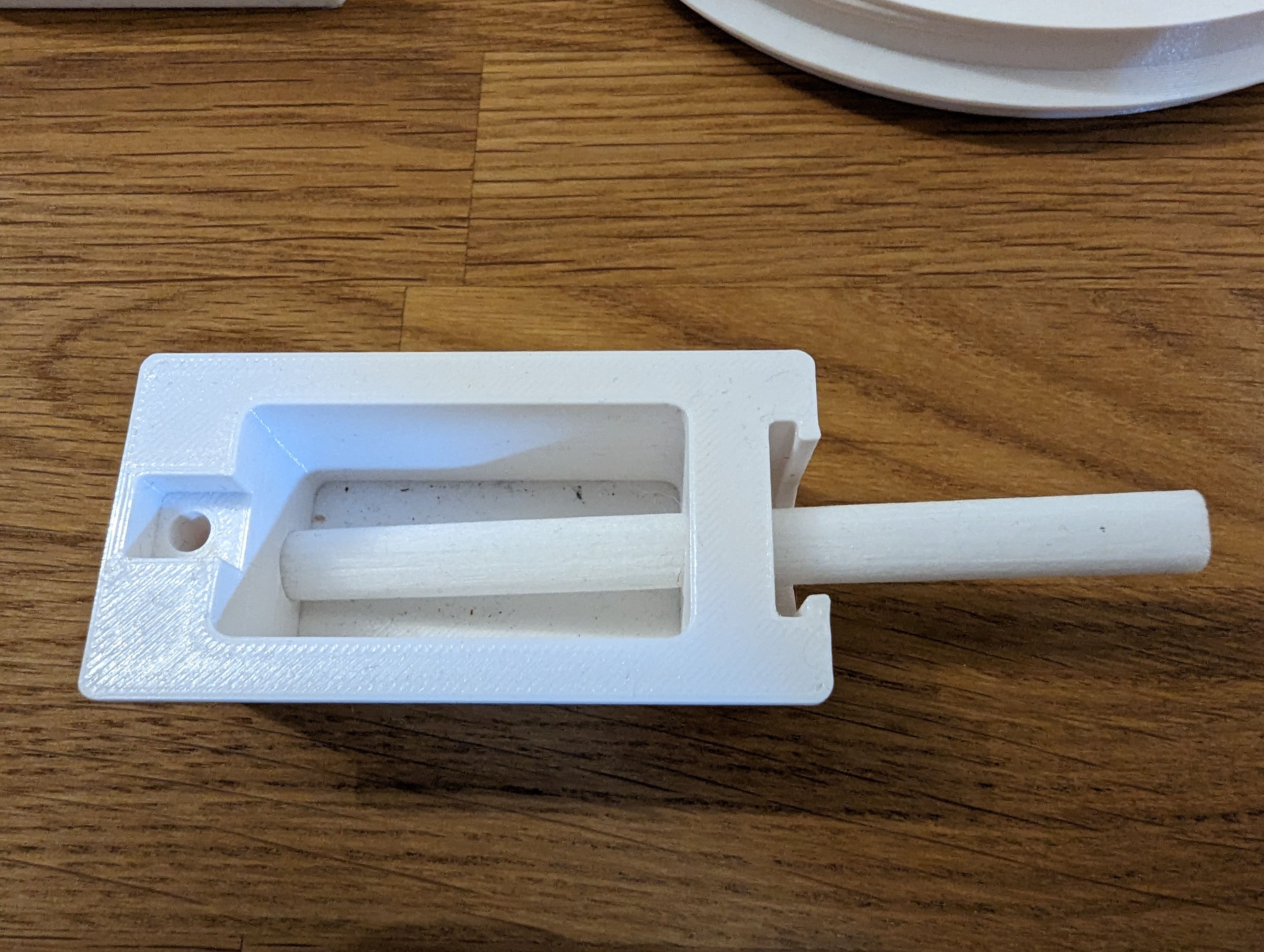
Cut off the overhanging part of the cotton stick, so that the piezo disk can fit in. Take the piezo with the solder joints facing outwards and slide it into the slot. The cotton stick should touch the piezo, to lead the water to it.
Be very careful with the piezo, as the cables can easily break of the disk.
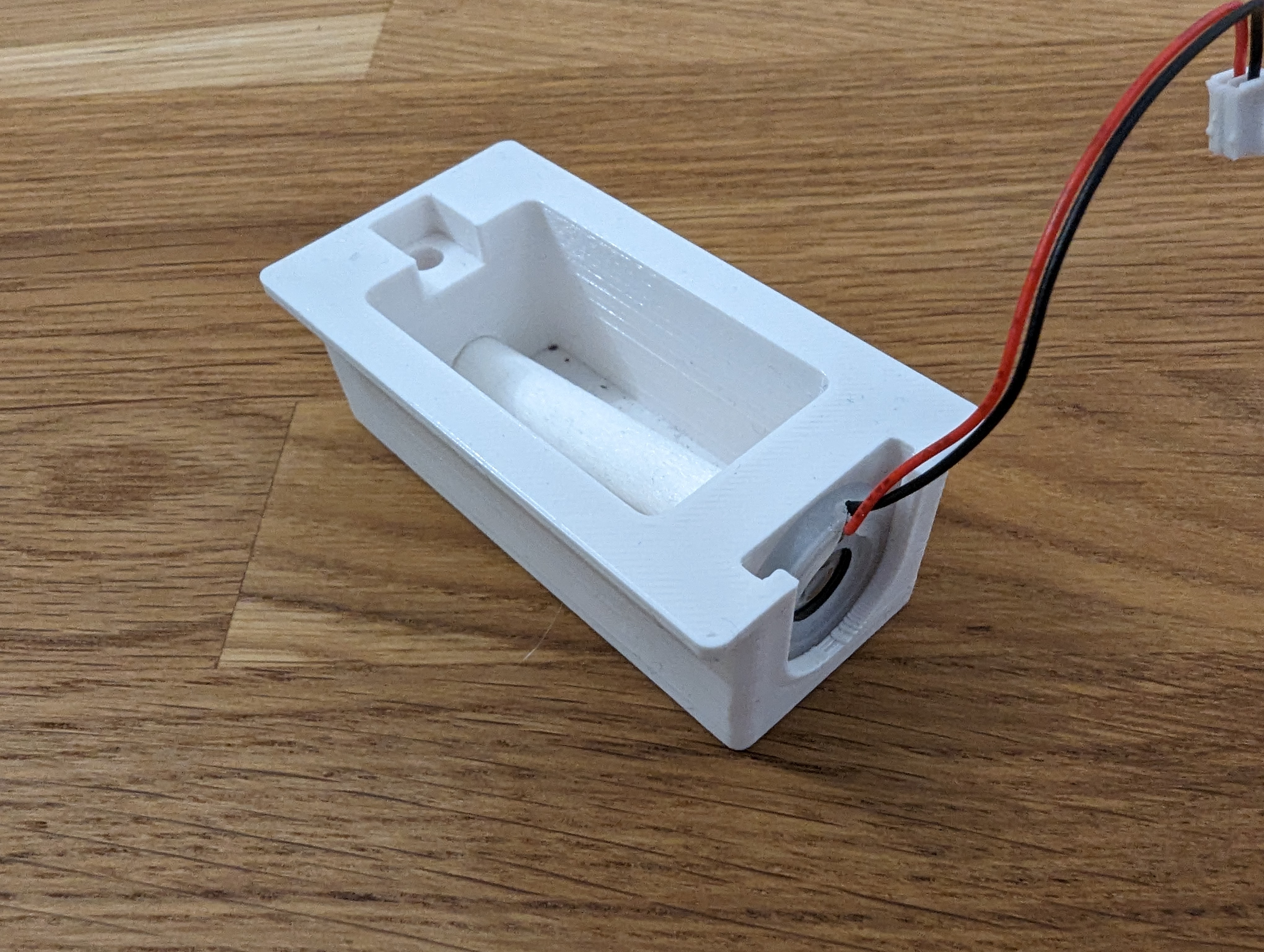
Mount the tank into the head mount and push it down, until it fits completely.
It is helpful to place the head mount onto a box (like the electronics lid (opens in a new tab)) to prevent the tank from being pushed out again.
Next, slide the electronics case into its slot. The atomizer module should be placed on the same side as the piezo cable. Be careful to fit the cables into the small cutouts on the mount and electronics case.
It should look like this.
Now take the tube and turn the head mount to see the pump section.
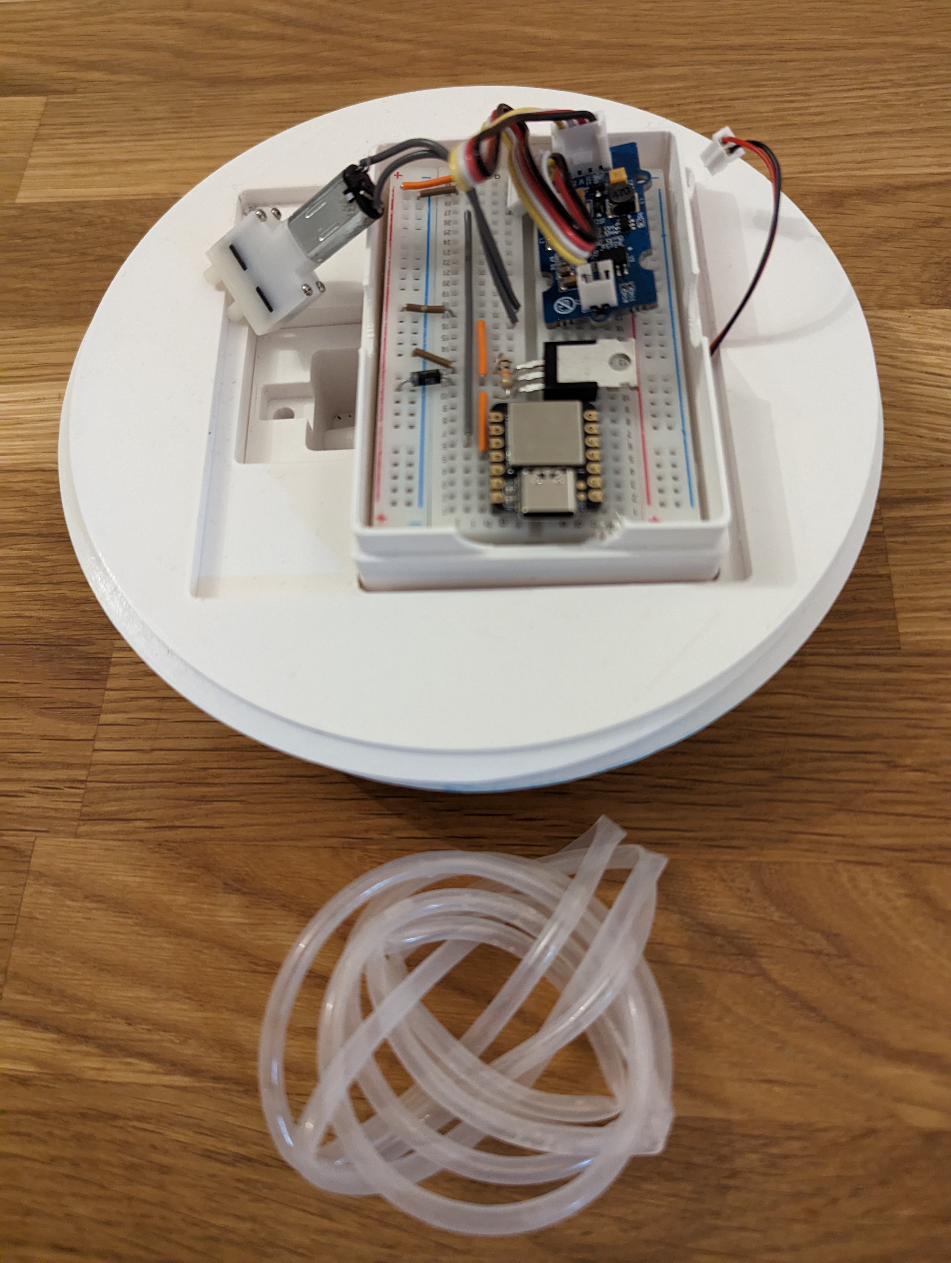
Stick the tube through the bottom hole of the tank.
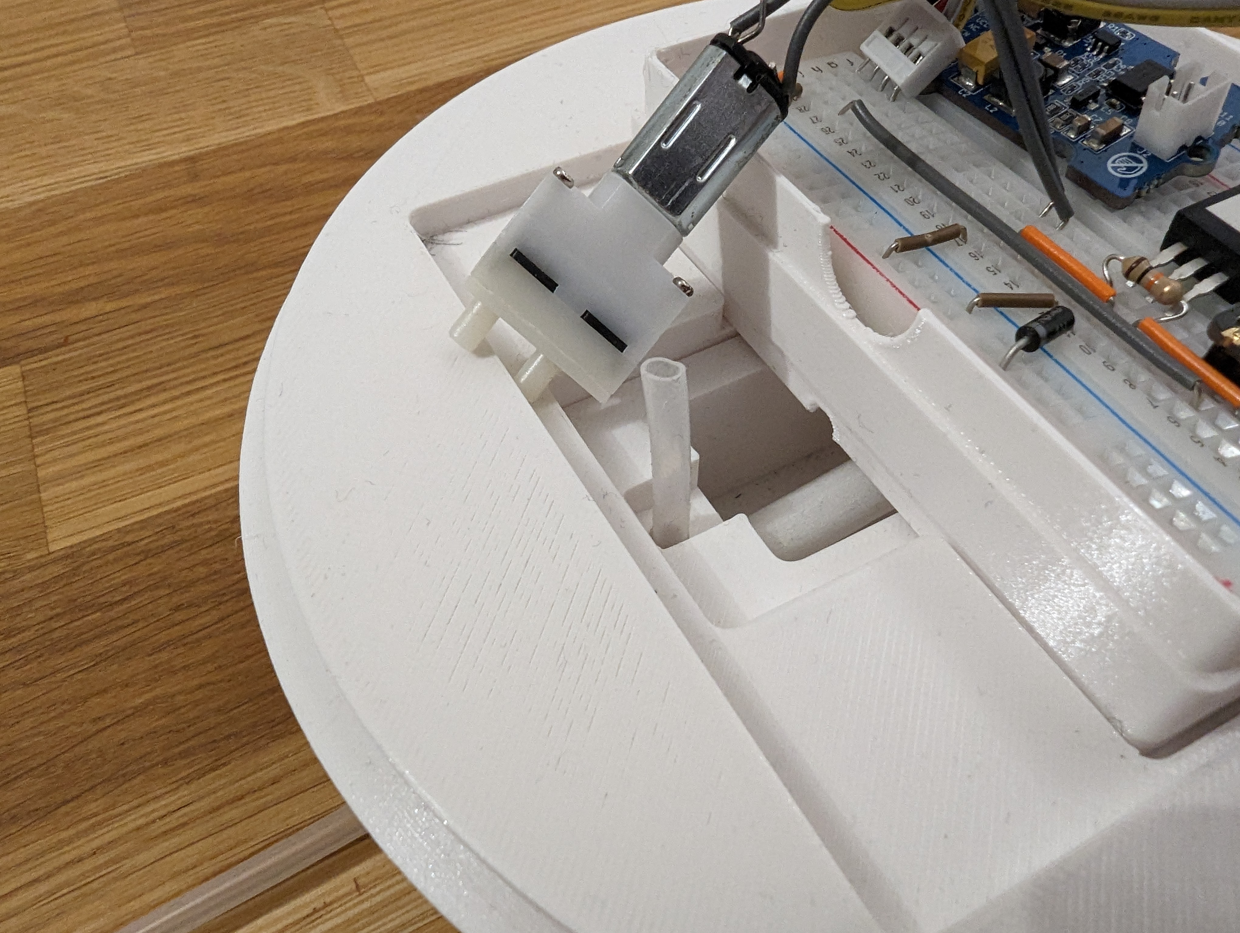
Connect the tube with the outer pin, which is the water intake. The pin at the center is the water outlet, respectively.
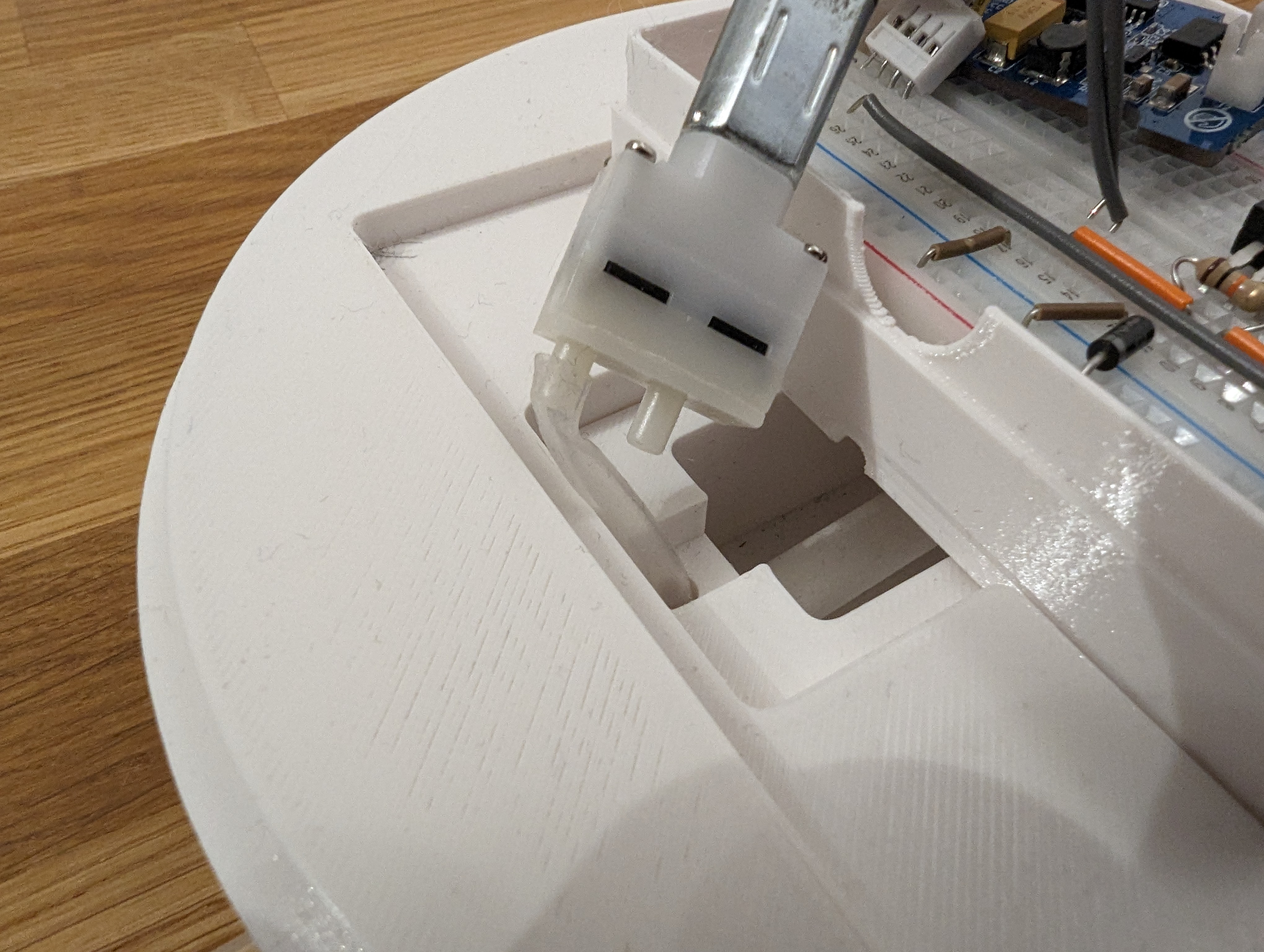
Push back the pump with the tube so that the pump fits into the cutout completely.
Connect the piezo cable with the socket on the atomizer module.
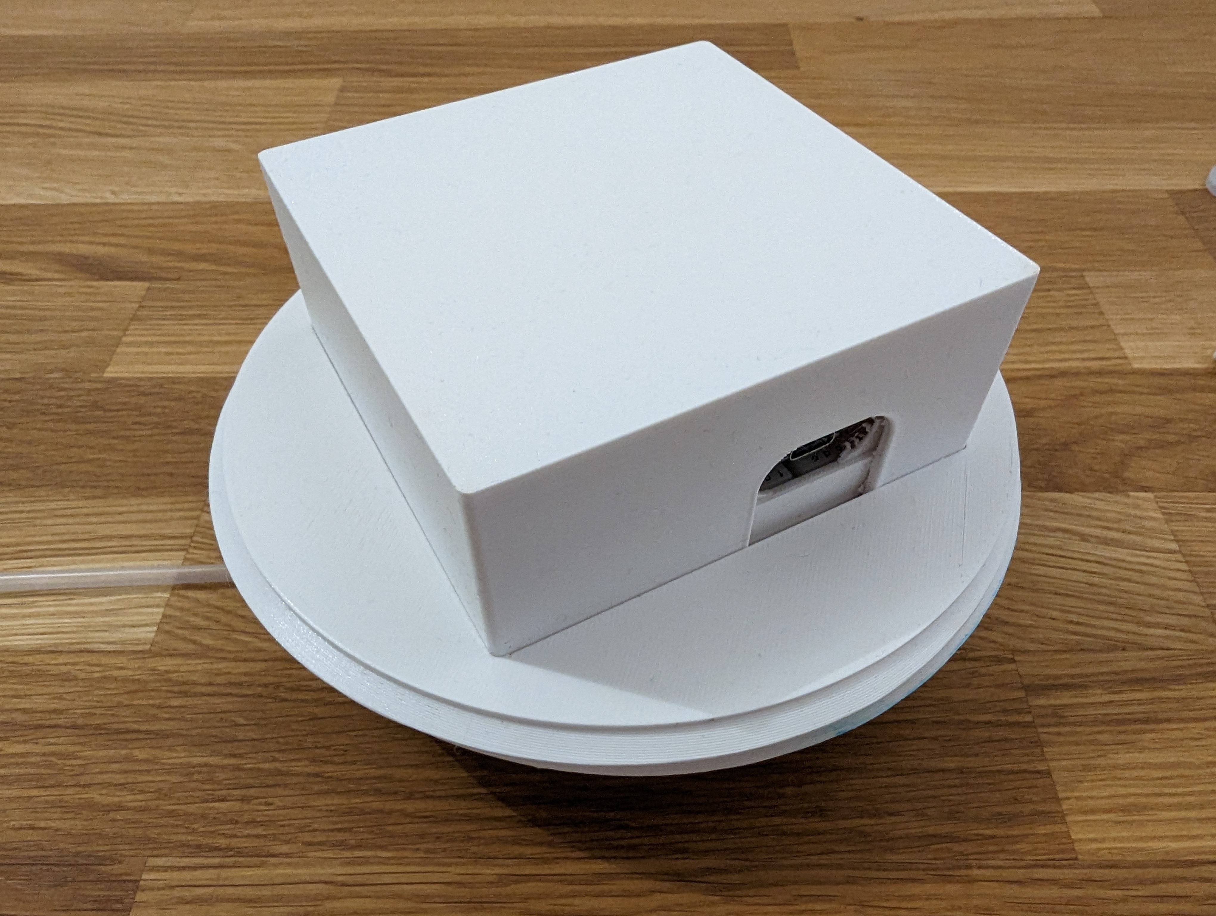
Lastly, you can cover the electronics with the lid (opens in a new tab).
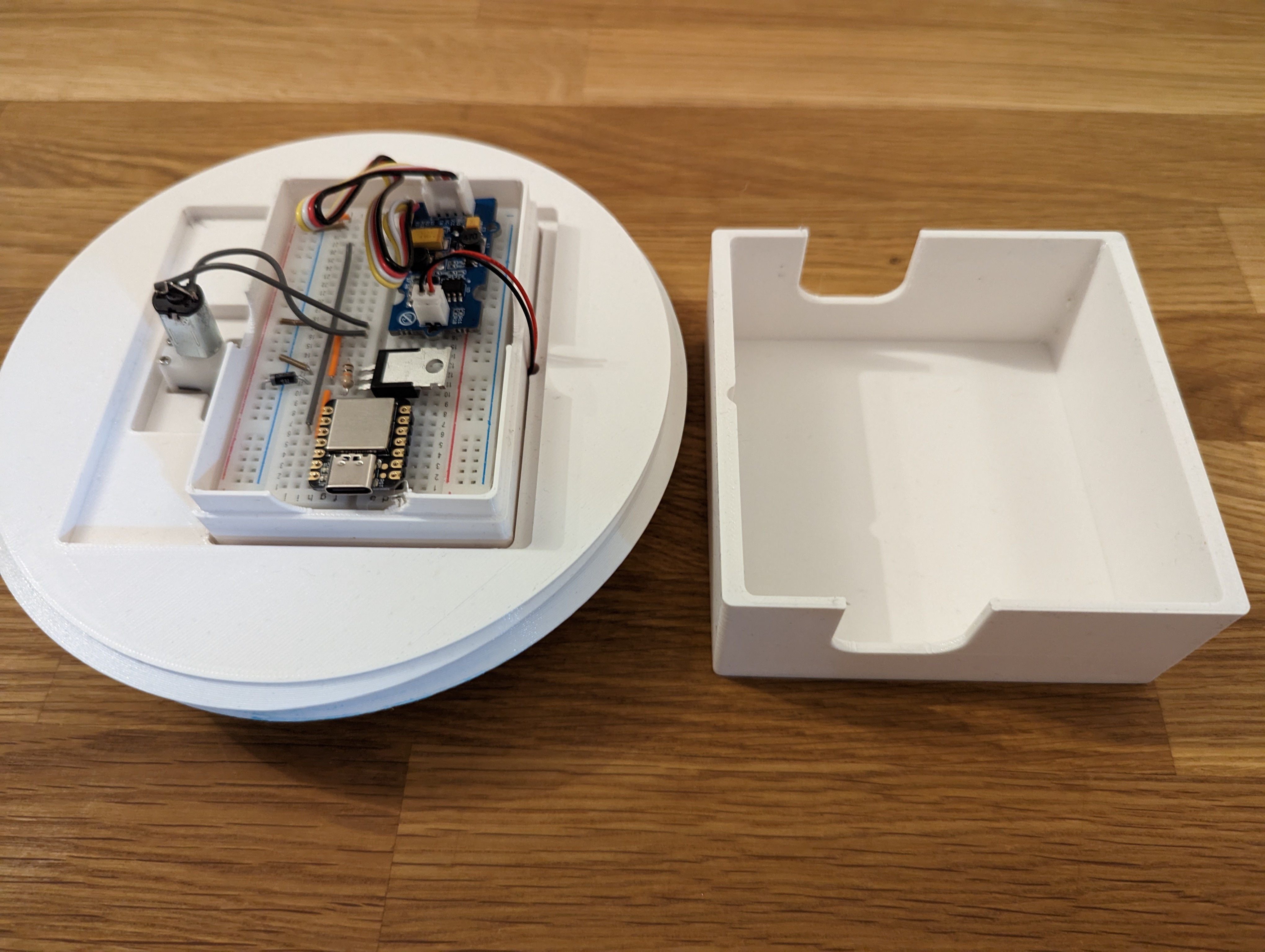
The USB port should still be visible, allowing you to power the device with any USB power adapter. Alternatively, you can use a solar power bank to place the whole tower outside and make it self sufficient.
Congratulations!!
You have built the electronics of the AeroTower. Now you can mount the head into the rest of the tower and test your setup. If you want to extend your tower further and power it by solar, you can look at this page.
Happy growing!